Support and fixing plane
Confirm the background condition, frame or rail spacing, fixing zones, panel support, removable areas and adjustment available during installation.
Interior wall-panel specification
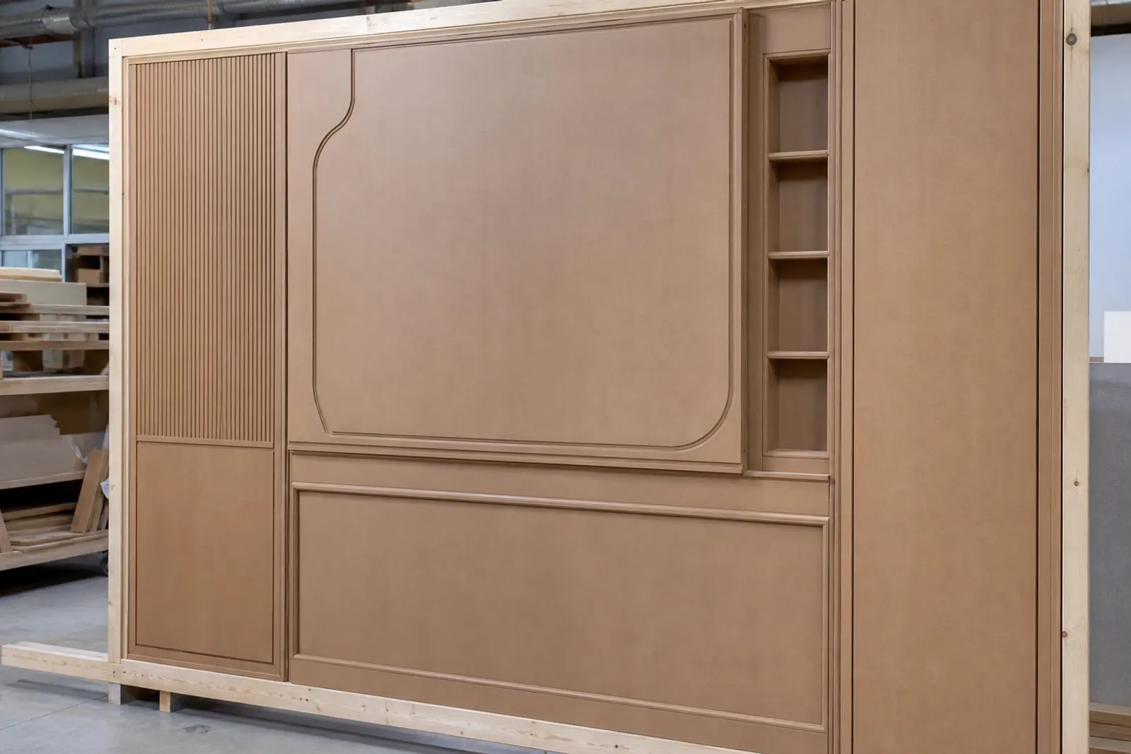
Connect wall elevations, module joints, support and fixing interfaces, decorative direction, service openings, required documents and installation-sequence packing before ordering interior MDF panels.
Direct answer
Treat the MDF panel, wall support, fixing method, visible joints and service openings as one coordinated assembly.
Start from the complete wall elevation. Define the background or frame, support plane, fixing zones and module grid before selecting the MDF and finish. The complete elevation confirms joint alignment, fixing access and the intended installation sequence.
Confirm the background condition, frame or rail spacing, fixing zones, panel support, removable areas and adjustment available during installation.
Coordinate face and reverse, veneer or pattern direction, edge treatment, joint width, adjoining modules and appearance under representative lighting.
Resolve corners, end returns, doors, ceilings, skirting, sockets, vents, signs, access panels and transitions to adjoining materials.
Approve several adjoining finished panels with a representative joint and the relevant corner or opening. This wall-scale reference reveals accumulated tolerances, grain-sequence changes, joint drift and device-alignment problems across adjoining modules.
Module decision matrix
The elevation should show how each module connects to the wall, adjacent materials and installation sequence.
| Wall component | Material option to compare | Critical information | Approval point |
|---|---|---|---|
| Flat wall modules | Veneer, laminate, melamine, paint or another approved faced MDF construction | Elevation grid, finished size, joint gap, visible edges, face and reverse, pattern direction, background support and fixing zones | Dry-fit several adjoining modules and check the wall-scale joint rhythm |
| Veneered sequence panels | Natural veneered MDF with drawing-defined matching and layout | Species, veneer cut, matching method, panel sequence, grain direction, balancing back, finish, joints, returns and acceptable variation | Approve adjoining finished panels in elevation order under representative lighting |
| Painted, routed or grooved panels | Paint-grade or decorative MDF selected for the complete routed and coated construction | Pattern geometry, groove depth, remaining section, first and last groove, module edges, coating inside profiles and repair method | Approve multiple finished modules, including a joint, perimeter and representative opening |
| Removable access panels | Wall-panel construction coordinated with the access and retention system | Access size, release method, frame or support, gaps, concealed or visible hardware, service clearance, orientation and replacement identity | Operate the finished access panel in the representative wall assembly |
| Service openings and integrated elements | Drawing-controlled MDF modules with finished cut edges | Sockets, switches, lighting, vents, screens, doors and other openings; datums, clearances, edge finish and responsible trade | Fit representative devices and verify alignment across adjoining modules |
| Trims, corners and transitions | Solid, laminated, veneered, painted or routed detail selected from the wall design | Inside and outside corner section, end return, skirting, ceiling and doorway transitions, shadow gaps, tolerances and site adjustment | Approve the finished transition as part of a multi-module mock-up |
Wall and fixing interface
Coordinate MDF module dimensions with the background plane, edge support, fixing method and accumulated joint tolerance.
Record the wall or frame construction, plane, moisture condition, obstructions, perimeter references and responsible site tolerances.
Show rails, battens, frames, mechanical fixings, approved adhesive interfaces where applicable and support at module edges and openings.
Coordinate panel sizes, joint gaps, corners, skirting, ceiling, doors, sockets, vents and access panels on one released elevation.
Inspect adjoining modules, joints, openings, returns and the proposed installation sequence before repeating the complete elevation.
Wall-scale finish control
Control the complete visible construction and record how it continues across joints, corners, openings and replacement panels.
| Finish construction | Typical module | What must be specified |
|---|---|---|
| Natural veneered MDF | Sequenced wall modules and premium visible fields | Specify species, cut, matching, sequence, grain direction, balancing back, finish, joint appearance and natural-variation boundary. |
| Painted or routed MDF | Solid-colour flat, fluted, grooved and relief panels | Define substrate, routed profile, remaining section, face and edge preparation, primer, topcoat, colour, gloss and coating inside grooves. |
| Laminate or melamine-faced MDF | Repeatable decorative modules and protected commercial interiors | Define face and reverse construction, décor, texture, direction, edges, joints, cut-out finish and permitted batch boundary. |
| Decorative and mixed-material modules | Feature fields, inserts, trims and panels adjoining metal, stone, fabric or lighting | Approve material junctions, thickness changes, shadows, tolerances, adhesives or mechanical interfaces and replacement method. |
Failure analysis
Visible wall defects often originate in the background, module grid, services, lighting or unsupported performance assumptions.
| Observed problem | What the symptom may indicate | How to control the order |
|---|---|---|
| Straight panels form an uneven finished wall | The existing wall, frame or furring plane was not surveyed, levelled or coordinated with panel thickness and fixing points. | The responsible designer and installer define the support plane and adjustment method; verify it with the representative panel system. |
| Joint lines drift across a long elevation | Module dimensions, common datums, joint gaps, site references and accumulated manufacturing or installation tolerances were not controlled together. | Use one elevation grid, inspect several adjoining modules and state where adjustment or site trimming is permitted. |
| Veneer grain or decorative pattern breaks at joints | Panel sequence, direction, matching method or front-face identification was absent from drawings, labels or packing. | Number every elevation panel, approve adjacent pieces and preserve the sequence from production through installation. |
| Sockets, vents or access panels are misaligned | Architectural, MEP and panel drawings used different revisions, datums or finished-wall assumptions. | Coordinate one released opening schedule, verify actual device templates and trial representative interfaces before machining the batch. |
| Grooves look uneven under grazing light | A small central sample did not reveal joint transitions, profile consistency, coating inside grooves or machining marks across modules. | Approve multiple finished panels under representative lighting, including joints, edges and openings. |
| A fire or acoustic result is assumed from the visible panel | The project treated a board name, red colour, groove or perforation as proof for the complete wall assembly. | Identify the required method, classification and assembly scope; review current product- and system-specific test reports before making a claim. |
Mock-up and installation release
The mock-up should include representative joints, installation sequence, openings, corners, lighting and site interfaces.
Assign room, elevation, module, top/bottom and visible-face IDs that remain consistent across drawings, labels and packing lists.
Inspect gaps, alignment, veneer or pattern continuation, groove rhythm and transition to adjacent modules.
Fit representative sockets, vents, lighting, screens and removable panels; verify clearance and edge finish.
Approve inside and outside returns, doorways, skirting, ceiling details, shadow gaps and permitted site adjustments.
Link project fire, acoustic, emission or other requirements to the exact product or assembly test report and its stated coverage.
Protect faces, corners and routed profiles; support large panels and pack modules in the agreed elevation order.
Interior wall-panel RFQ
Keep unresolved background, fixing and project-document questions visible so every supplier prices the same defined assumptions.
Relevant MDF products
Use the module matrix to compare these options. Final construction, required documents and installation suitability remain order-specific.
Control veneer species, cut, matching, sequence, grain direction, balancing layer and finished wall appearance.
View product →Product optionSpecify custom visual surface, texture or pattern with a representative module and approved junction details.
View product →Product optionDefine groove section, pitch, module alignment, remaining material, finish and protective packing.
View product →Product optionCoordinate smooth faces, routed profiles, cut edges and the complete coating system.
View product →Product optionReview the exact board classification and document coverage against the intended complete wall construction.
View product →Product optionControl openings, profiles, fixing zones and repeated geometry through released drawings and first-article checks.
View product →Buyer questions
Use these answers to identify missing module, support, finish and document inputs before quotation.
MDF can be reviewed for protected-interior wall modules when the background, support, fixing interface, module and joint design, surface, edges, openings, room conditions and installation are specified together. Exterior exposure and uncontrolled wet conditions require a construction designed and qualified for those environments.
There is no universal thickness. Review module size, support spacing, fixing method, routed depth, remaining section, openings, edge details, finished weight and the complete wall design. The responsible designer must confirm the supported assembly.
Define the visible joint type and gap, module grid, common datum, support at edges, pattern or grain continuation, corner and perimeter transitions, manufacturing tolerances and permitted installation adjustment before cutting panels.
A selected MDF product may have a classification under a stated test method, but that result does not automatically classify the finished wall with facing, coating, adhesive, cavity, backing and fixings. Match project requirements to current supporting documents for the relevant product or complete assembly.
Acoustic performance is established for the complete system, including groove or perforation geometry, open area, backing, cavity, insulation, module joints and installation, supported by applicable system test reports.
Send elevations, module and joint schedules, support and fixing details, surfaces and edges, veneer or pattern direction, service openings, corners and transitions, project required documents, mock-up plan, installation-sequence packing, destination and timing.
Application to specification
Send elevations, module and joint schedules, background and fixing details, surfaces, openings, transitions, project required documents, mock-up plan, installation-sequence packing, destination and timing. CUZI MDF will review the order-specific requirement.