
Draw the groove section
Specify width, depth, pitch, radii and remaining core below the groove. The land between adjacent grooves is a different dimension.
Professional MDF Manufacturer & Supplier
Bring depth and rhythm to your furniture and interior panels. Our Shuyang factory machines Grooved MDF Panels to your section drawings, with groove spacing, module joints and finishing details prepared for your design.
Technical specification
Grooved MDF Panels have drawing-defined decorative channels or fluting machined into MDF. Specify the groove section, panel dimensions and supplied finish for furniture and interior wall designs.
Finish and processing
Specify width, depth, pitch, radii and remaining core below the groove. The land between adjacent grooves is a different dimension.
Set panel widths, edge lands, joint gaps and pattern direction together. Number modules and compare adjoining panels before repeating the layout.
Cutting through a veneer or facing can expose the MDF core. Define the finish inside grooves and on edges; decorative grooves alone do not establish acoustic performance.
Selection guide
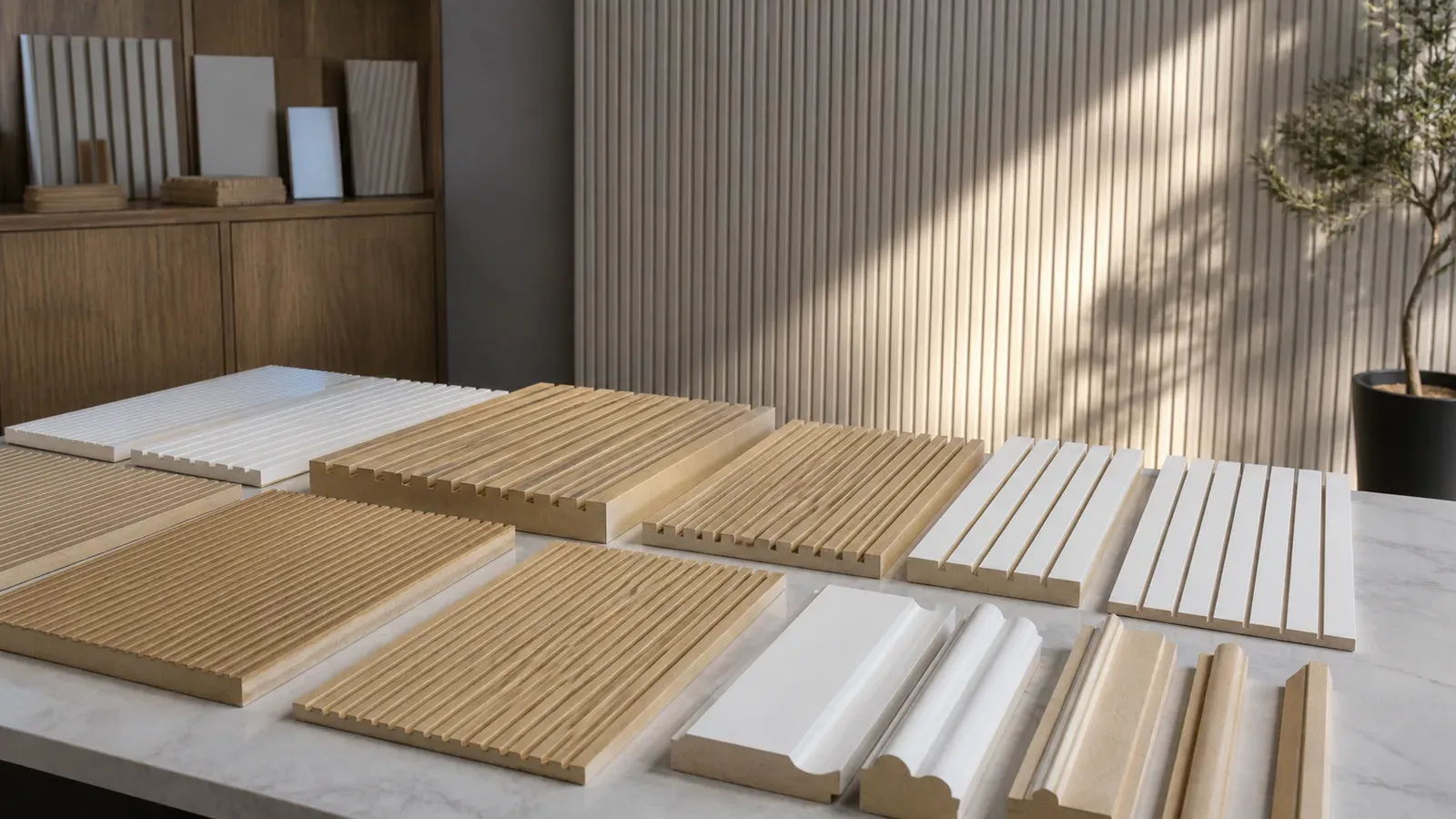
Grooved MDF Panels turn a flat MDF face into a repeated decorative surface. Straight channels, V-shaped details and rounded or fluted effects create different lines, shadows and finishing needs. Choose the section with a physical sample, then plan how it continues across the furniture part or wall layout. A consistent pattern depends on the groove geometry, finish and adjoining modules together.
CUZI MDF manufactures and supplies drawing-defined grooved panels from our factory in Shuyang, Jiangsu, China. Order raw machined panels for your finishing process, or discuss the specified primer, paint or faced construction. Send the finished module dimensions, groove section, layout and quantities so we can quote the actual core, machining and supplied stage. The sample and drawing connect the design to the panels your team receives.
| Purchasing purpose | Construction information to identify | Relevant product or system |
|---|---|---|
| Decorative face pattern | Visible groove width/depth/pitch, finish, margins and module joints | Drawing-defined Grooved MDF Panels |
| Curved component | Actual flexible-board or back-kerf construction, direction, support and trial | Separate curved-panel specification and representative sample |
| Sound-absorbing lining | Through/opening geometry where used, backing, cavity and mounting | Complete tested acoustic assembly |
| Retail hanging panel | Functional slot section, insert/fitting, support and load conditions | Slotted MDF retail system |
Our Flexible MDF is a separate 3–6 mm thin-board product that bends longitudinally as a continuous sheet. A proposal using grooves cut into the back to help form a curve describes another construction. Specify its kerf geometry, remaining face, support and trial separately when discussing a curved component. A decorative face-groove drawing supplies the appearance geometry for this page's primary use.
For acoustic work, identify how the actual system admits sound to its backing and absorbing layers, and match the panel to the tested construction. A decorative blind groove shapes the face; an acoustic assembly has its own openings, layers, cavity and fixing requirements. See acoustic panel substrates or Perforated MDF for the corresponding request. Slotted MDF Panels covers retail fittings and their functional interfaces.
Give the profile a section drawing as well as a face view. Groove width is the opening measured at the drawing's stated reference. Depth is measured from the original core face to the deepest machined point. Pitch is the distance between corresponding points of successive grooves, normally their centre lines for a repeated straight-channel pattern. Record groove direction, start/end treatment, tool shape, root radius and fixing or cut-out clear zones.
Rounded and fluted effects need their actual section: crown, valley, root shape and reference face. A photograph communicates appearance; the section and dimensions establish the machining. Identify whether measurements refer to the machined core or the completed coating/facing. Surface layers can affect the final groove opening, corner definition and overall thickness, so the finished sample belongs with the dimensional reference.
| Geometry field | Drawing reference | Useful calculation or check |
|---|---|---|
| Input core thickness T | Unmachined MDF thickness | Actual core measurement and required grade |
| Groove opening w | Width at the stated section/face reference | Opening and profile shape after the supplied finish |
| Routing depth d | Original core face to deepest cut | Nominal remaining core = T − d |
| Repeat pitch p | Centre-to-centre or stated matching points | Nominal land between equal straight grooves = p − w |
| Pattern phase | First groove centre from the module datum | First/last groove positions and edge margins |
| Groove length and direction | Face-view axes and defined ends | Orientation, end margins, interrupted areas and clear zones |
For an illustrative 18 mm core routed 6 mm deep on one side, nominal remaining core is 18 − 6 = 12 mm. This calculation describes geometry. The actual core, remaining section, supports, fixings and intended use establish the component design. Check actual thickness and depth on a representative part, including any nearby cuts or hardware recesses.
Our input MDF range is 2–35 mm, with the existing density bands, six listed board formats and nominal ±0.1 mm core thickness tolerance subject to the agreed measuring method. Select the actual core thickness with the requested cut. Machining tolerances, finished module dimensions and groove/profile acceptance are separately agreed from the drawing. The input range describes board capability; the qualified section describes your grooved component.
The European Panel Federation routing guide discusses routing MDF and choosing cutting conditions for the operation. Tooling, preparation and process for the actual profile are established on the selected board. Retain the drawing and first-component checks for repeat machining. Our CNC MDF Processing page covers the wider drawing-defined parts service.
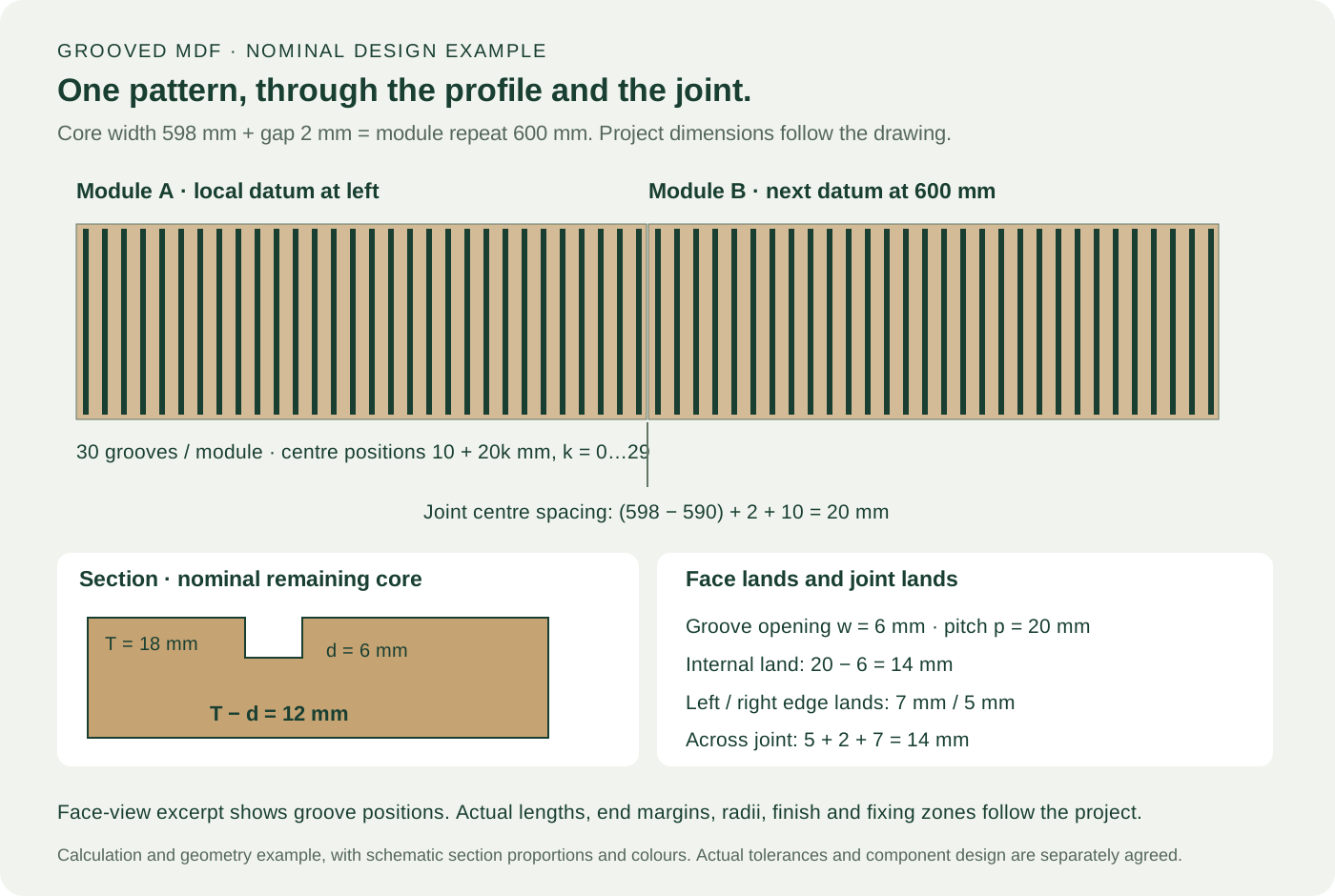
Plan the module width and installation gap with the groove phase. The distance between the last groove of one panel and the first groove of its neighbour includes the remaining distance to the first panel's edge, the gap, and the neighbour's first-groove offset. Two identical-looking panels can give a different rhythm at their joint when those references change.
The diagram uses a nominal straight-channel example to make that relationship visible. Each core module is 598 mm wide, with 6 mm groove openings at 20 mm centre pitch. The first groove centre is 10 mm from the left datum; centres continue at 30, 50 and every 20 mm to 590 mm, giving 30 grooves. The illustration shows a 2 mm gap and the next module beginning 600 mm from the first module's datum.
| Illustrative layout field | Nominal input or calculation | What it controls |
|---|---|---|
| Core module width | 598 mm | Actual machined panel width in this example |
| Groove centres | 10 + 20k mm, k = 0…29 | 30 grooves, first at 10 and last at 590 mm |
| Groove opening and internal land | 6 mm; 20 − 6 = 14 mm | Channel opening and material between channels |
| Edge lands | Left 10 − 3 = 7 mm; right 598 − 590 − 3 = 5 mm | Material from the groove opening to each outside edge |
| Joint and module repeat | 2 mm gap; 598 + 2 = 600 mm | Position of the adjoining module's left datum |
| Centre spacing at the joint | (598 − 590) + 2 + 10 = 20 mm | A 20 mm repeat across the seam |
The unequal 7 mm and 5 mm edge lands are intentional in this nominal example: 5 + 2 + 7 = 14 mm across the joint, matching the internal land. The gap itself remains a separate installation detail. This is a calculation and drawing example, with the project designer setting the actual width, gap, clearances, profile and tolerances. It supplies a method for checking a proposed layout. Each order defines its actual panel specification.
In the face view, grooves run vertically along the module; all positions above are measured horizontally from its left datum. The section uses T = 18 mm and d = 6 mm to show 12 mm nominal core beneath the cut. Actual groove length, end margins and module height belong in the project drawing. Keep these references with the face/reverse orientation and module ID.
For a complete wall, add starts and ends, internal/external corners, returns, openings and any trimmed modules. A rotated or shortened panel can need a separate pattern phase or edge detail. Use a module elevation and quantities by ID, then inspect an adjoining-module sample with the actual finish and intended gap before producing the panel set. Interior wall-panel guidance helps organize that layout.
The face, groove floor, walls, corners and outside edges need their respective supplied finish. Raw grooved MDF can be prepared for your workshop's coating system. Primer or completed paint supply uses the specified materials, preparation, coverage and cured appearance. A high-gloss or fine rounded detail can make surface marks and shape changes more visible, so use the representative profile in the finishing trial.
Routing a previously veneered or faced board can expose MDF inside the groove. Specify whether that cut remains a deliberate contrasting surface, is painted, or receives another compatible treatment. A continuously faced shaped profile describes a different facing process and needs its own material/profile trial. Keep grain or pattern direction with the module layout and reverse construction.
| Supplied condition | Finish information to agree | Representative sample to inspect |
|---|---|---|
| Raw machined core | Core, machining/sanding state and next coating process | Face, groove floor/walls, outside edge and narrow detail |
| Primed grooved panel | Named primer/system, preparation, coverage and delivered stage | Profile retained after preparation and primer |
| Completed paint | Colour/gloss reference, compatible coating and cure/handling guidance | Cured appearance through grooves and across adjoining modules |
| Grooved pre-faced board | Existing facing, exposed-core treatment and reverse | Groove edge quality, cut colour, grain direction and joint |
| Continuously faced shape | Actual facing/adhesive, qualified profile and supplied build | Contact through the shape, corner and reverse transition |
The EPF guidance on sanding profiled edges connects surface preparation with retaining the profile. Its edge-finishing guidance discusses finishing machined MDF edges. Use the selected coating or facing supplier's instructions and the actual component trial to establish preparation, materials and process. Keep those instructions with the sample and order.
Choose Paint Grade MDF for the corresponding painted-core request, Veneered MDF for a natural wood-face construction, or PVC Faced MDF for compatible formed-film profiles. Grooved-panel manufacture still follows the exact profile, module and supplied condition in your order. This keeps the finishing responsibilities clear between our factory, your workshop and the installer.
Use at least two adjoining representative modules when the design depends on pattern continuity. Identify the core grade/thickness, drawing revision, profile/tool reference, finish, datum edges, module IDs and intended gap. Compare first/last groove positions, width, depth, pitch, remaining core, machining marks, outside edges and completed dimensions against that record.
Check colour, texture, shadows and visible seams under the agreed light and viewing conditions. A small profile offcut shows the section and finish preparation; adjoining modules add the joint and repeated appearance. For a shaped corner or opening, include a representative return or cut edge where it affects the design. Keep the completed sample and inspection references for the next order.
For an installed lining, the designer's support, fixing and clearance details belong with the elevation. Identify fixing zones and remaining material at those positions; include services, openings, corners and substrate condition. Component thickness and a decorative groove alone describe part of the design. The actual mounting, support and use establish the installed assembly, with any required fire or acoustic result matched to its tested construction.
Select the MDF core and full finish for the room conditions. Protected dry and humid interiors have different grade, coating and joint needs. Machined grooves and new site cuts expose additional core surfaces; specify their preparation and final treatment with the operation. Retain reverse-face protection and material-specific installation or care guidance for the completed panel set.
Protect narrow lands, shaped ridges, groove edges and corners during handling and packing. Use clean suitable separators, flat support and protective cover boards with contact and strap positions suited to the actual profile. Labels connect each module and its orientation to the elevation, so unpacking and installation follow the planned sequence. Dimensions, density, supplied finish and handling determine the pack and loading arrangement.
Send a design reference with front and section drawings, core grade/thickness, groove width/depth/pitch, direction and margins. Add finished module sizes, wall or furniture layout, quantities by ID, joint gaps, returns, openings, support/fixing zones and destination. State the supplied stage: raw machined, prepared for coating, primed, painted or the identified faced construction. We reply within 12 hours to help complete the request.
FOB China price: US$2–8/m² for Grooved MDF Panels. Your formal quote identifies the area basis, actual board, pattern, machining, finish and supplied condition. Confirm included and separately priced work, edging/returns, sample preparation, identification and protective packing. Installation hardware or installation work is included only where expressly listed with the order's scope.
Samples are free across our range and generally in stock. You cover courier cost, which can be credited against a formal order. For a custom profile or adjoining-module sample, we confirm the drawing, material/finish, preparation, dispatch and estimated transit for your address. Request the representative geometry needed for your decision so the sample supports machining, finishing and layout checks together.
Normal MOQ is 1 × 20'GP per specification. Normal production lead time is 3–10 days after specification and commercial confirmation, with groove machining and further finishing scheduled for the actual area, profile and quantity. MDF board production capacity is 500 m³ per day across the factory; grooved or finished-component output follows the selected operations. Third-party inspection is supported.
Your quotation includes specifications, quantity, price/currency, packaging, FOB Qingdao or FOB Lianyungang, lead time, T/T or LC terms and validity. Shipments use Lianyungang or Qingdao, with loading based on sizes, density and packing. Keep the core, profile, layout, finish, sample and module labels as the repeat-order reference, and identify revisions that affect the panel set.
Applications
Order flat, veneered or grooved wall panels with the openings, trims and finish your interior needs. Our Shuyang factory supplies boards and machined modules to your elevation, keeping panel positions, adjoining finishes and installation packs coordinated.
Explore applicationCreate your feature wall with grooved, fluted, veneered or CNC-profiled MDF panels. Our Shuyang factory coordinates modules, corner returns and trims around your elevation, with the selected raw, primed or finished supply and clearly identified packs.
Explore applicationMachined substrates for a specified acoustic assembly. Performance depends on the backing, absorber, cavity and mounting as well as the panel.
Explore application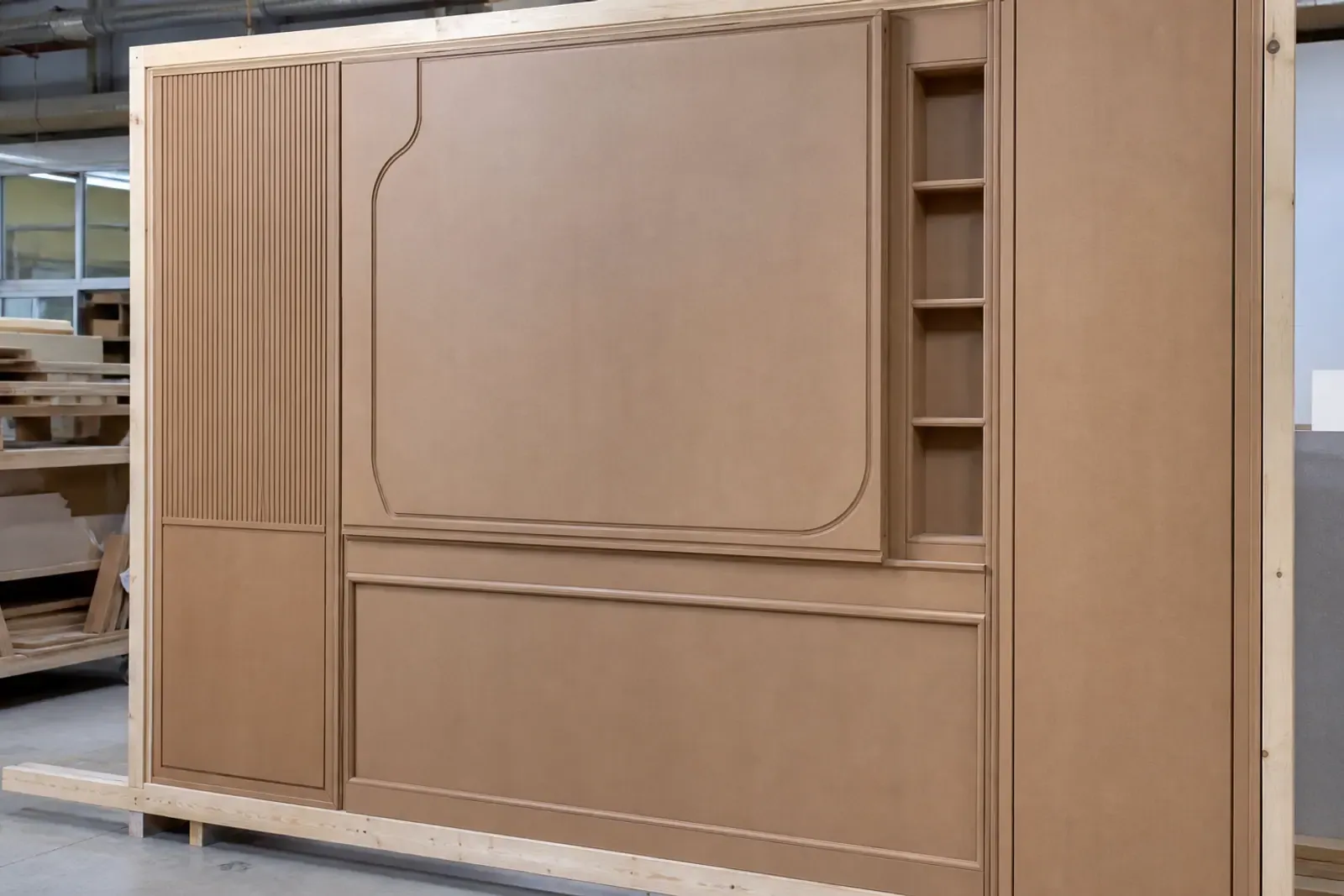
Boards and components
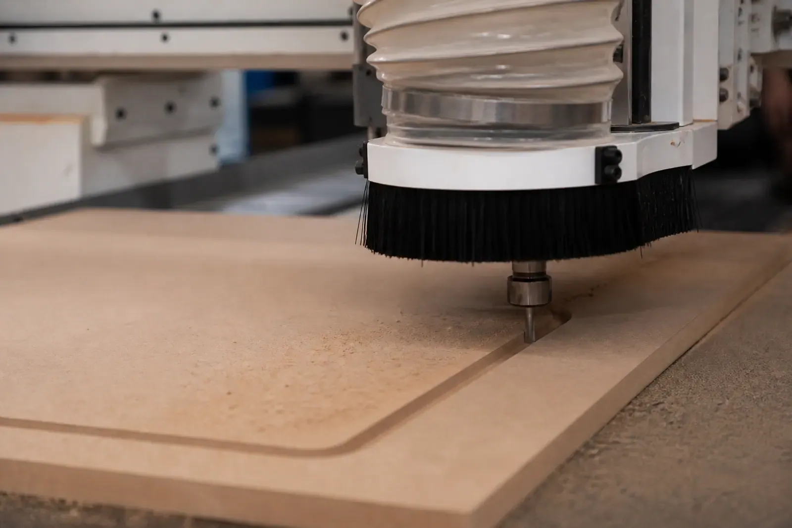
Request core and finish documents plus profile and module inspection records. Acoustic claims require results for the complete installed system, including backing and cavity.
Made in Shuyang, China
Work with Shuyang Cuzi MDF Co., Limited on board selection, machining, inspection and export packing. Our factory has a total daily production capacity of 500 m³ across its operations.
Made to order. The usual minimum is 1 × 20'GP per specification; mixed sizes or finishes are quoted together. Delivery lead time starts after specifications and terms are confirmed; sea transit is scheduled separately.
Freight is calculated for your ports and cargo quantity. Returns and exchanges, including timing and costs, are agreed in the order.
Delivery and freight terms · Returns and 180-day warranty · Packing and loading information
US$2–8 per m²
Your quotation confirms the specification, quantity, packaging and final price.
Buyer FAQ
Grooved MDF here describes decorative surface geometry. Slotted retail panels use a profile designed to accept specified inserts or display fittings. Send the required section and end use so the quotation identifies either a decorative groove or a functional hanging slot.
Width describes the groove opening, depth is measured from the original face to its deepest point, and pitch is the distance between matching points of adjacent grooves. The section drawing also needs the bottom shape, while the elevation fixes direction and margins.
Use a common datum and a module schedule. Define the last groove and edge margin of one panel together with the first groove and margin of its neighbour, including the intended joint gap. Approve an adjoining-module sample before producing the full set.
Yes, with the exposed-core finish specified wherever routing passes through the veneer. Agree grain direction, groove-edge quality and groove colour or coating. A continuously veneered shaped profile uses a separately confirmed facing construction.
Samples are free and usually in stock. You pay the courier charge, which can be credited against your order. Send the sample details and delivery address for availability, courier cost and timing. We will also give you a preparation date for custom samples.
Subtract routing depth from input core thickness. An illustrative 18 mm core routed 6 mm deep leaves 12 mm nominal core beneath that cut. Check actual thickness/depth and include nearby cuts, supports and fixing details in the component design. The calculation describes geometry; the actual design establishes suitability.
A decorative face groove establishes visible geometry. Back kerfs for a curved component need a separately identified cut pattern, remaining face, support and qualified trial. Our Flexible MDF is a separate 3–6 mm continuous thin sheet that bends longitudinally; specify the actual curved-panel construction with the request.
Specify the complete acoustic assembly, including its opening geometry, backing/absorbing layers, cavity, mounting and finish. The actual tested construction establishes the absorption result. Decorative blind grooves establish face geometry and appearance; an acoustic project needs its corresponding system specification.
Buyer guides
Protect decorative MDF faces and edges during export. Plan separators, covers, supports, labels and loading around your panel sizes and delivery route.
Read guideSpecify Flexible MDF around the finished curve, its support and the chosen finish. CUZI MDF supplies 3–6 mm whole thin sheets for longitudinal bending.
Read guidePlan MDF interior wall panels with a complete elevation. Coordinate module sizes, panel joints, service openings, supports, finish and installation quantities.
Read guideDimension grooved MDF profiles, pitch, remaining core and panel joints. Work through corner returns, end details and a four-module feature-wall layout.
Read guideSend a profile drawing or design reference, finished module sizes, quantities, finish and destination. Add the wall elevation, joints and fixing zones where relevant. We reply within 12 hours to help with a free sample and quote.