Module geometry and joints
Define the booth grid, finished dimensions, shared datums, joint gaps, connector zones, remaining section, floor or frame interface and adjustment available on site.
Exhibition stand and flat-pack component specification
Turn the booth design into controlled modules, joints, finishes, graphics, part labels and packs that can reach the venue, assemble in sequence and withstand the agreed reuse plan.
Direct answer
Start with the stand modules, venue access, assembly sequence and reuse plan before selecting the board and finish.
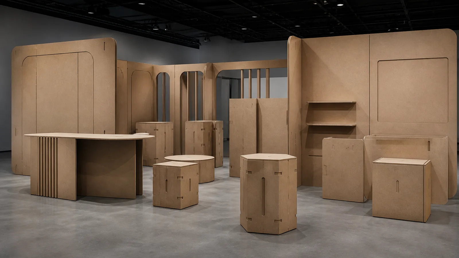
Break the stand into identified wall modules, counters, plinths, storage, graphic panels and connector-controlled parts. Each item needs a released drawing, face and edge construction, hardware group, quantity and position in the build sequence.
Define the booth grid, finished dimensions, shared datums, joint gaps, connector zones, remaining section, floor or frame interface and adjustment available on site.
Coordinate faces, edges, direction, applied graphics, lighting, power, cable routes, access panels and adjoining modules on one released elevation.
Set the largest pack from venue access, label parts and hardware by assembly step, protect reused edges and complete a build-disassemble-repack trial.
A workshop trial should reproduce the real connectors, representative services and installation order. Record the accepted stand revision before dismantling it, then inspect joints and edges during repacking so the complete module provides the basis for each reuse decision.
Exhibition component matrix
An exhibition package combines display surfaces, reusable structures, services and replaceable visual parts. Quote each component against its real role.
| Stand component | Material option to compare | Critical information | Approval point |
|---|---|---|---|
| Backdrop and wall modules | Raw, paint-grade, melamine, laminate or decorative MDF selected for the finished wall | Module grid, overall elevation, joints, frame or floor interface, service openings, graphic zones, end returns and installation sequence | Dry-fit adjoining modules with the real connectors and representative floor or frame interface |
| Plinths and display tables | Finished MDF construction coordinated with its support, edge and intended exhibit | Footprint, finished height, internal frame, levelling, access, exhibit size and weight, visible faces and handling points | Assemble the complete supported unit and verify it with a representative exhibit |
| Counters and storage units | Melamine, laminate, veneer, paint or another approved face/back/edge construction | Worktop support, doors, locks, shelves, equipment, cable routes, ventilation, service access and customer-facing edges | Build one complete counter bay with hardware and service interfaces |
| Graphic and signage panels | Smooth painted, laminated or graphic-ready MDF substrate matched to the specified fixing method | Artwork size, bleed, direction, adhesive or fixing method, cut-outs, edge treatment, change frequency and removal plan | Approve the actual graphic process on a finished representative panel |
| Replaceable decorative skins | Thin or standard MDF component selected for the released module and reuse plan | Attachment points, panel direction, finished dimensions, removal clearance, replacement reference and protection between events | Fit and remove the replacement face without damaging the reusable structure |
| Knock-down parts and connector zones | Cut-to-size and CNC-machined MDF parts controlled by part ID and revision | Joint type, connector, hole pattern, edge distance, tool radius, repeated-assembly expectation, handed parts and spare quantity | Complete one assembly-disassembly cycle and inspect every reused joint |
First build and release
The first assembly must verify fit, access and appearance, then show whether the same components can be identified, protected and rebuilt.
Connect booth boundaries, shared datums, module IDs, part quantities, handed components and the approved drawing revision.
Use the released connectors, hardware, lighting, power and cable interfaces to verify the complete assembly.
Review faces, edges, joints, graphics, profiles, sightlines and lighting across representative module boundaries.
Record damaged or replaceable parts, reconcile hardware and prove that labels and pack order support the next installation.
Finish and graphic control
Colour, gloss, grain, profile and graphics can change across joints or under strong directional light. Record the complete visible construction.
| Surface construction | Typical component | What must be specified |
|---|---|---|
| Painted MDF | Branded solid colours, routed features and seamless-looking display fields | Approve substrate, profile, face and edge preparation, primer, topcoat, colour, gloss, repair reference and protection during transport. |
| Melamine or laminate-faced MDF | Repeat flat modules, counters, storage and high-contact display parts | Define face and reverse, décor or laminate, texture, direction, balancing construction, edge band, joints, openings and cleaning route. |
| Veneer or decorative MDF | Premium walls, counters, plinths and focal display elements | Control species or décor, cut and matching where relevant, direction, sequence, balancing back, edges, finish and acceptable variation. |
| Applied graphics | Campaign panels, logos, information boards and replaceable visual skins | Trial the actual film, print, adhesive or mechanical fixing on the selected finished substrate; record artwork orientation, cut-outs, removal and residue expectations. |
Failure analysis
Short installation windows magnify missing data. Resolve the complete module and logistics path before changing the MDF description.
| Observed problem | What the symptom may indicate | How to control the order |
|---|---|---|
| The stand fits in the workshop but not at the venue | Venue access, lift or doorway limits, booth boundaries, floor condition, build height or on-site assembly clearances were not included in the module plan. | Record the access envelope and venue restrictions before freezing module and pack dimensions; dry-fit within the released booth grid. |
| Joints loosen or edges break after repeated assembly | Connector choice, remaining MDF section, edge distance, tool radius, handling method or expected reuse cycles were not reviewed together. | Test the real connector through assembly and disassembly, inspect the joint and define replaceable parts and spares. |
| Graphics or grooves lose continuity across modules | Artwork, profile origin, module datum, joint gap and installation order used different references. | Release one coordinated elevation with shared datums and approve adjoining finished modules before repeat machining. |
| Installation stops when parts or hardware lack traceable identification | Labels and packing lists did not connect stand, module, part, handed orientation, hardware group and assembly step. | Carry one controlled part ID from drawing to label, hardware bag, pack list and installation sequence. |
| The shipment reaches the venue with packs outside the handling limits | The largest pack, centre of gravity, forklift or trolley access, manual handling limit and unloading route were not defined. | Set pack dimensions from the complete logistics route and identify lifting, orientation and opening sequence on every pack. |
| Reused modules no longer match visually | Finish batches, repair references, graphic revisions, directional faces and replacement panels were not retained by event or module. | Keep approved finish references and part history; review visible replacements beside retained or installed components. |
Venue-ready packing
The correct components must move through the venue and reach the installer with their connectors, orientation and revision intact.
Record vehicle, unloading, pallet, lift, doorway, corridor and booth access limits before setting module and pack dimensions.
Carry event, stand, module, part, handed orientation and revision from drawings to labels and packing lists.
Bag and identify connectors, fasteners, brackets, locks and service fittings by module and assembly step.
Use clean separators, corner and edge protection and continuous support suited to routed profiles and reusable faces.
Arrange packs so base, frame, wall, counter, graphic and trim modules can be opened in the agreed build order.
Define how parts are inspected, relabelled, protected and reconciled after dismantling for the next event.
Exhibition display RFQ
Keep unresolved venue, connector and compliance questions visible so every quotation uses the same defined assumptions.
Relevant MDF products
Use the module matrix to compare these options. Final construction, required documents and suitability remain order-specific.
Prepare rectangular display parts from controlled cut lists with part IDs, direction and pack sequence.
View product →Product optionControl knock-down joints, connector holes, profiles, service openings and repeated machining through released drawings.
View product →Product optionCoordinate smooth faces, routed edges and the complete coating process for branded exhibition components.
View product →Product optionSpecify laminate, balancing face, edges, joints and openings as one finished display construction.
View product →Product optionControl repeat décor, texture, face/reverse construction, direction and edge band for modular display parts.
View product →Product optionReview visual surfaces, routed patterns and approved appearance references for focal stand elements.
View product →Buyer questions
Use these answers to identify missing module, venue, finish and packing inputs before quotation.
MDF can be used for protected-interior exhibition walls, counters, plinths, graphic panels and storage when each component is designed around its support, joint, finish, handling and venue conditions. Stability, structural design, fire or venue compliance and safe installation remain requirements of the complete stand and responsible project parties.
The choice depends on the component. Paint-grade MDF supports painted and routed parts, melamine or laminate supports repeat flat modules and storage, decorative or veneered MDF controls premium appearance, and cut-to-size or CNC services prepare drawing-controlled knock-down parts.
Provide the stand and module map, part drawings, units and revision, joint and connector details, face and edge construction, hardware groups, assembly order, venue access limits, largest pack, reuse expectation, labels, spares and destination.
Reuse depends on the complete module, connectors, remaining material around joints, edge protection, assembly method, storage and handling. A first build should include disassembly, inspection and repacking so damaged or replaceable parts are identified before shipment.
Approve the actual print, film, adhesive or fixing method on the selected finished MDF. Check colour and gloss, adhesion, panel joints, cut-outs, direction, removal and residue. A digital artwork file alone does not define the finished substrate interaction.
Send the booth and module drawings, component schedule, surfaces and edges, graphics, connectors and hardware, services, venue and access limits, first-build plan, reuse expectation, part labels, pack dimensions, spares, destination and event deadline.
Application to specification
Send booth and module drawings, finishes, graphics, connectors, services, venue access limits, quantities, trial-build requirements, reuse plan, assembly-sequence packing, destination and deadline. CUZI MDF will review the order-specific requirement.