Machining geometry
Release opening shape, size, pitch, pattern origin, border zones, groove depth, remaining ribs, panel datums and tolerances in one revision-controlled drawing.
Acoustic panel substrate and machining specification
Connect the machining drawing to the specified backing, cavity, mounting and applicable system test reports. The supplied MDF component is one controlled part of the complete acoustic assembly.
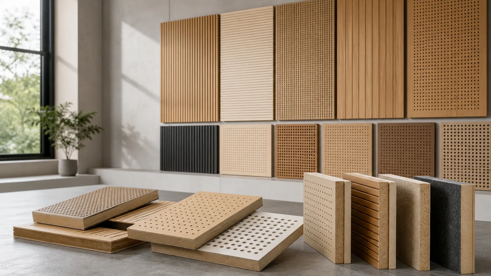
Direct answer
The order must reproduce the geometry and construction reviewed for the complete acoustic system, not only the appearance of the MDF face.
Begin with the system drawing and applicable performance test reports. Identify the exact substrate, thickness, perforation or groove pattern, finish, backing, absorber, cavity and mounting arrangement. If any layer changes, the responsible designer must decide whether the acoustic test report still applies.
Release opening shape, size, pitch, pattern origin, border zones, groove depth, remaining ribs, panel datums and tolerances in one revision-controlled drawing.
Connect the panel to its face finish, backing or fabric, absorber, cavity depth, frame, fixings, module joints and perimeter conditions.
Measure a representative machined and finished panel, inspect blocked openings and breakout, then map the accepted construction to the applicable report.
Nominal open area describes geometry; it does not establish NRC, absorption coefficient or another acoustic result. Performance claims must come from a test report that covers the relevant complete assembly and test method.
Acoustic system matrix
Similar-looking panels can belong to different acoustic constructions. Quote each component against the exact system drawing and approval point.
| System component | Material option to compare | Critical information | Approval point |
|---|---|---|---|
| Perforated face panels | Drawing-controlled MDF or HDF substrate with specified face and reverse construction | Hole shape and diameter, pitch, pattern origin, border zones, open area, panel thickness, finish, backing and mounting grid | Measure a first panel and compare the exact complete assembly with the applicable design or report |
| Slotted face panels | MDF substrate selected for the released slot geometry and remaining section | Slot width and length, end radius, pitch, edge distance, unmachined zones, face direction, backing and cavity | Inspect slot position, breakout, remaining ribs and adjoining-module alignment |
| Grooved or routed modules | Raw, paint-grade, veneered or decorative MDF construction matched to the section drawing | Groove profile, width, depth, pitch, material remaining below the route, module joint and coating inside the profile | Approve a section sample and adjoining finished modules under representative lighting |
| Backing and absorber interface | Buyer-specified fabric, fleece, absorber or other backing used within the complete system | Material reference, thickness, density where relevant, adhesive or fixing method, coverage, orientation and relationship to openings | Confirm the supplied backing and attachment match the construction covered by the responsible system review |
| Cavity, frame and mounting parts | Panels and trims manufactured to the designer's module and fixing layout | Cavity depth, support spacing, rails or clips, fasteners, removable panels, service openings, perimeter details and installation sequence | Build a representative bay with the specified support, cavity and interfaces |
| Edge, corner and access modules | Drawing-defined MDF parts coordinated with the visible field and acoustic-system boundaries | Cut edges, returns, corners, doors, sockets, vents, access panels, trims, joint width and pattern termination | Approve the transition together with representative adjoining modules |
Document-matched release
Record the product, geometry and system layers covered by each cited report or target NRC.
Record the report or design reference, test method, result, specimen build-up and party responsible for applying it to the project.
Coordinate pattern, module joints, borders, openings and first/last positions across the complete elevation.
Inspect dimensions, pitch, open area inputs, groove depth, breakout, ribs, edges, finish and backing attachment.
Route any substrate, finish, backing, absorber, cavity or mounting change back to the responsible system designer before repeat production.
Face, finish and backing
Approve the actual machined and finished construction to reveal blocked holes, veneer breakout and backing coverage.
| Construction | Typical use | What must be specified |
|---|---|---|
| Raw or painted perforated MDF | Machined openings and painted interior panels | Define substrate, pattern, finish build, coating inside openings, colour and gloss. Check that primer or topcoat does not bridge or reduce designed openings. |
| Veneered MDF | Visible wall and ceiling modules with natural wood appearance | Specify species, cut, matching, direction, balancing back, finish and the sequence across joints. Confirm how perforation or routing affects veneer edges. |
| Melamine or laminate-faced MDF | Selected durable or decorative modules | Review face and reverse construction, direction, machining order, opening-edge condition, possible chipping or delamination, edge treatment and compatibility with the system test reports. |
| Backing and adhesive layer | Fabric, fleece or absorber interface behind openings | Identify the exact material and coverage, adhesive or mechanical attachment, blocked-area limits, overlap and installation responsibility; link the acoustic result to that exact backing construction. |
Failure analysis
Diagnose an acoustic-system issue by comparing the installed construction, machining and cited test report with the released assembly.
| Observed problem | What the symptom may indicate | How to control the order |
|---|---|---|
| The installed system does not match the quoted acoustic value | The test or design used a different substrate, hole pattern, finish, backing, cavity depth, absorber, mounting or panel layout. | Map every claimed value to the exact report and complete assembly; send substitutions to the responsible acoustic designer before production. |
| Paint or adhesive blocks openings | The finishing process was approved on a flat colour sample while the representative machined panel and backing-adhesive coverage remained unverified. | Approve the actual finish and backing process on a representative machined panel and inspect openings against the released drawing. |
| Patterns drift at panel joints | Each panel was programmed from its own edge without one elevation datum, joint gap or first/last pattern position. | Release the complete elevation with shared datums and inspect multiple adjoining modules before repeat machining. |
| Thin ribs break or openings chip | Slot pitch, tool diameter, tool condition, feed, panel support or material remaining between openings was not verified by a first article. | Trial the most demanding geometry, measure the remaining section and approve machining quality before the full batch. |
| Panels arrive bowed or machined faces are damaged | Large open areas, thin remaining sections, uneven strap pressure or incomplete flat support increased handling stress. | Use continuous flat support, clean separators, edge and corner protection, controlled strap positions and module labels. |
| The certificate or report lacks order traceability | The document identified a different product, thickness, construction or test assembly, or the supplied part IDs did not preserve the approved revision. | Create an document register connecting report, construction, drawing revision, sample, part ID and inspection release. |
Inspection and protective packing
Machined panels can be more vulnerable than plain sheets. Inspection and packaging should follow the released panel and installation sequence.
Check opening size, pitch, pattern origin, borders, module joints and first/last positions against the controlled drawing.
Inspect breakout, chipped faces, tool marks, blocked openings, groove depth, remaining ribs and cut-edge condition.
Verify face direction, coating inside openings, adhesive coverage, backing reference, orientation and attachment.
Use continuous level bearers, clean separators and strap positions that preserve perforated fields and narrow ribs.
Carry elevation, module, part, face orientation and revision IDs from drawings to labels and packing lists.
Group matched or directional panels in the released order and protect corners, edges and visible faces from hardware.
Acoustic substrate RFQ
Identify which values are design requirements, which document applies and which construction details remain unresolved.
Relevant MDF products
Use the component matrix to compare these options. Acoustic performance remains tied to the applicable complete assembly.
Review the substrate, thickness, surface, machining and finish construction for drawing-controlled perforated or grooved components.
View product →Product optionCompare dense thin-panel options where the released component and system design require them.
View product →Product optionReview supported 2–11 mm components where the design accounts for flatness, handling and complete assembly support.
View product →Product optionControl groove section, pitch, remaining thickness, module alignment and finished appearance from a released drawing.
View product →Product optionSpecify slot geometry, inserts or backing interfaces, support, openings and the complete panel layout.
View product →Product optionPrepare repeated holes, slots, grooves, fixing points and module profiles from revision-controlled machining drawings.
View product →Buyer questions
Use these answers to identify missing geometry, construction and applicable test reports before quotation.
No. Perforated, slotted or grooved MDF is a machined substrate. Acoustic performance depends on the complete assembly, including geometry, finish, backing, absorber, cavity, support, mounting and installation. A panel appearance or nominal open-area calculation is not an acoustic rating.
The relevant variables can include the hole, slot or groove geometry, open area, panel and finish construction, backing material, absorber, cavity depth, framing, mounting, module joints and boundary conditions. Use a report or qualified system design that applies to the proposed complete assembly.
Provide panel dimensions, thickness, units and revision; pattern origin, pitch and first/last position; opening or groove section; unmachined borders; module joints; fixing and service zones; face direction; backing and cavity references; and part quantities.
A finish can alter openings, surface construction or the backing interface. Paint can bridge small holes, laminates or veneers change the face construction, and adhesive can block open area. Any change from the tested or specified assembly needs review by the responsible designer.
Check panel dimensions, pattern position, opening size, pitch, blocked openings, breakout, remaining ribs, groove depth, face direction, module joints, finish inside openings, backing attachment, part labels and protected flat packing.
Send the responsible system specification and applicable test reports and product documents, panel and pattern drawings, substrate and thickness, finish, backing and absorber references, cavity and mounting, module schedule, tolerances, first-article plan, packing, destination and requested timing.
Application to specification
Send the system specification and record or document reference, machining drawings, substrate, finish, backing, absorber, cavity, mounting, quantities, first-article requirements, packing, destination and timing. CUZI MDF will review the order-specific component scope.