
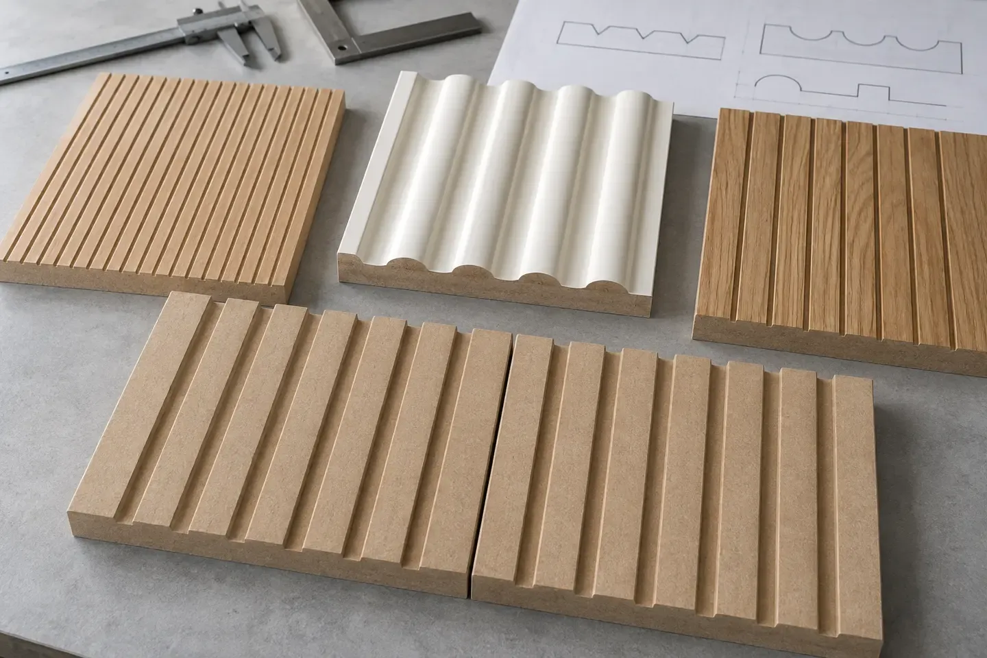
A grooved MDF specification combines a profile section, a panel elevation and an installation layout. These three views control groove geometry, pitch, remaining material, edge margins, module joints, corners, finish build and installation sequence.
Start with the finished visual result
Define the intended wall, door, furniture front, display panel or decorative component. Record the viewing distance, lighting direction, module sizes, joint locations, finish and installation order. The visible result sets the pattern and tolerance priorities for the drawings.
Distinguish grooves, profiles and functional slots
Use the machining description that matches the finished component.
| Machined feature | Main specification focus |
|---|---|
| Decorative groove | Width, depth, root shape, pitch, margins and coating build |
| Fluted or ribbed profile | Repeating section, peak width, valley geometry, direction and joint continuity |
| Relief pattern | Tool path, depth changes, local radii, pattern origin and edge termination |
| Functional slot or perforation | Opening geometry, spacing, backing or insert and complete-system requirement |
Acoustic, fire or load requirements follow the applicable tested product, assembly or engineering scope.
Define the profile section
Dimension every feature that controls the cut.
| Section item | Information to state |
|---|---|
| Board | Product, nominal thickness and face to be machined |
| Groove | Mouth width, depth, root width and root radius or shape |
| Side | Angle, radius, chamfer or stepped detail |
| Repetition | Centre-to-centre pitch and profile sequence |
| Remaining material | Minimum section beneath the deepest cut |
| Reverse operations | Rebates, pockets, drilling and fixing zones |
Use one drawing revision and one unit system across the section, elevation and cut list.
Define the pattern elevation
Dimension pattern direction, first-groove datum, pitch, panel width, edge margins and total module size. Identify centre lines, symmetry, deliberate pattern breaks and the visual relationship between adjacent modules. Mark the top and visible face so production, packing and installation share the same origin.
Control edge margins and the last groove
Show the distance from the first and last groove to each finished panel edge. Where a pattern centres on the module, define the centre datum and resulting edge margins. Where several modules form one elevation, calculate the last-to-first spacing across every joint and include the installed gap in that calculation.
Review remaining material and fixing zones
Overlay front grooves with rear fixings, hardware, rebates, pockets, connectors and edge profiles. Mark clear routing zones around fasteners and supports. The completed drawing should show the material remaining where front and reverse operations approach each other.
Resolve module joints and boundaries
Draw the pattern at the actual boundaries that shape the finished appearance.
- joints between adjacent modules;
- inside and outside corners;
- end returns and perimeter trims;
- doors, access panels and removable sections;
- sockets, controls and service penetrations;
- floor, ceiling and adjoining-material transitions.
State whether each boundary continues, centres, mirrors or deliberately stops the pattern.
Select the MDF substrate for the finish and environment
State raw, paint-grade, MR, HMR, veneered or another reviewed MDF construction according to the protected-interior environment, machining depth and finishing process. Link the selected board thickness and density expectation to the remaining section, edge detail and component handling plan.
Qualify the finish inside the actual profile
Trial sanding, cleaning, sealing, primer, topcoat, veneer or decorative treatment on the production profile. Review the groove root, side walls, peaks, inside corners and end grain. Coating build changes small radii and groove width visually, so the accepted sample should use the proposed preparation and complete finish system.
Approve two adjoining modules
Place at least two representative finished modules together with the intended joint gap and orientation. Review pitch continuity, last-to-first groove spacing, surface level, edge margins, corner strategy, finish build and lighting. Include a representative opening, return or termination detail in the approval set.
Translate the approved sample into production controls
Record the approved drawing revision, substrate, tooling reference where applicable, finish schedule and sample identity. Use named datums to measure the first groove, pitch, depth, panel dimensions and joint edges. Keep raw-machining checks and finished-appearance checks tied to the same part identity.
Inspect the production pattern
Review both geometry and the finished visual sequence.
| Inspection area | Review point |
|---|---|
| Individual profile | Width, depth, root shape, side quality and remaining section |
| Repeated pattern | Pitch, direction, first and last groove position |
| Panel | Dimensions, squareness, edge margins, face and top orientation |
| Adjoining pair | Joint gap, cross-joint spacing, level and pattern continuity |
| Finished surface | Groove coverage, colour, sheen, clean edges and lighting response |
Label and pack by installation position
Mark module ID, elevation, top, visible face and sequence. Protect raised edges, finished profiles and corners with suitable separators and rigid support. Arrange packs in the planned receiving and installation sequence so each module remains traceable through unpacking and placement.
Buyer review checklist
Before releasing a grooved or profiled MDF order, confirm:
- the finished elevation and intended visual origin are defined;
- the profile section states width, depth, root geometry and remaining material;
- pitch, direction, first groove and edge margins are dimensioned;
- front machining, reverse operations and fixing zones are coordinated;
- joints, corners, openings and perimeter terminations are drawn;
- the actual substrate and full finish system appear in the sample;
- two adjoining modules demonstrate cross-joint continuity;
- inspection datums, labels, sequence and packing follow one drawing revision.
Request an MDF quotation
Send the elevation, profile section, substrate, thickness, finished module schedule, finish system, quantity, sample scope, inspection plan, labels, packing and destination. Use Grooved MDF Panels for decorative groove scope, Slotted MDF Panels for functional slot requirements, and request a drawing and quotation review.