
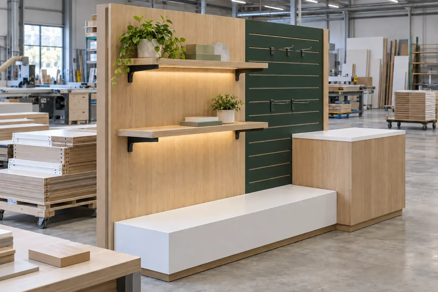
Retail fixture production converts a store design into repeated wall bays, counters, display units, shelves, plinths and branded panels. A controlled module schedule connects every component to its finish, machining, hardware, location, revision, inspection and installation pack.
Start with the store rollout and installation plan
List every store, format, zone and installation phase. Record whether each location uses a standard fixture package, a mirrored arrangement or site-specific dimensions. Connect quantities and delivery dates to store IDs so production, packing and replacement parts follow the same rollout plan.
Divide the store design into controlled modules
Separate wall bays, gondolas, counters, display plinths, shelving, drawers, doors, signs, graphics carriers and decorative panels. Give each module a drawing, bill of parts, finish code, hardware set, installation position and revision.
Create a component schedule
Translate every module into repeatable part families.
| Component family | Information to control |
|---|---|
| Wall or freestanding back panel | Finished size, face/reverse, fixing zones, service openings and joint position |
| Shelf or display deck | Span, support, edge, bracket interface, finished load and quantity |
| Counter or plinth | Plan geometry, corner construction, visible faces, base interface and access panels |
| Door or drawer front | Finish direction, edge, gap, hardware and handed orientation |
| Slotted or routed display panel | Slot pattern, pitch, edge margin, remaining section and approved accessory |
| Sign or graphic carrier | Graphic size, fixing points, lighting interface and replacement method |
Use the same part code across drawings, machining files, inspection records and pack lists.
Describe the service environment and contact zones
Map customer touch points, product contact, cleaning frequency, trolley or basket impact, lighting heat, entrances, food-service adjacency and protected interior humidity. Assign surface, edge and corner decisions to each component according to its actual position in the fixture.
Specify the complete panel construction
Record MDF product, thickness, finished dimensions, face material, reverse material, edge construction and supplied processing stage. State whether the order covers full panels, rectangular cut parts, routed parts, edge-banded components, drilled sets or assembly-ready modules.
Control brand finishes across the store
Use physical references for colour, texture, gloss, veneer, paint, laminate and edge materials. Review adjacent panels under representative store lighting and beside metal, glass, acrylic and graphics. Record grain or pattern direction, matched elevations and the accepted range of natural variation.
Define slotted, routed and accessory interfaces
Issue a controlled pattern drawing showing slot or groove width, depth, pitch, start position, edge margin, radii and remaining section. Identify the actual hook, bracket, rail or accessory model and review its fit in a representative machined panel before repeat production.
Coordinate loads, supports and fixings
The fixture designer establishes the completed system's shelf loads, bracket spacing, anchoring and stability. Show the resulting rails, inserts, brackets, bases, wall fixings and support zones on the component drawings. Supply the current hardware for machining and first-assembly review.
Coordinate lighting, power and graphics
Map every service interface before releasing machining.
| Interface | Drawing information |
|---|---|
| LED channel or light box | Profile, recess, cable route, ventilation and access |
| Power or data point | Cut-out, clearance, fixing and service path |
| Digital screen | Bracket pattern, ventilation, cable exit and removable access panel |
| Graphic panel | Finished size, registration, fixing and change method |
| Security device | Equipment reference, cable path and protected mounting point |
Review openings with the current accessory or interface drawing.
Translate the site survey into adjustable interfaces
Record wall condition, floor level, ceiling and skirting dimensions, columns, service points, loading access and elevator limits. Use fillers, scribes, levelling provisions and defined installation gaps where the store design accommodates site variation. Keep site-specific parts linked to the correct store and zone.
Control joints, corners and customer-facing edges
Define module gaps, panel joints, corner returns, shadow lines, exposed openings and transitions into adjoining finishes. Review prominent corners and high-contact edges as assembled samples so colour, texture, joint line, radius and touch quality are clear.
Build a representative installation bay
Dry-fit a bay or complete fixture that contains the main construction decisions. Review:
- module dimensions, squareness and joint gaps;
- shelves, brackets, rails, doors and drawers;
- lighting, cable, graphic and accessory interfaces;
- finish direction, edge appearance and adjoining materials;
- assembly sequence, adjustment and tool access;
- labels, pack contents and site handling.
Record the accepted modules, parts and drawing revisions before repeat production.
Plan seasonal changes and replacement parts
Identify shelves, graphics carriers, doors, high-contact panels and accessories expected to change during the store life. Use stable part IDs, accessible fixings and retained surface references. Record the construction and revision of installed parts so future additions can be reviewed against the current store.
Control revisions across a multi-store rollout
Record the effective store, phase or production quantity for every approved drawing, finish and hardware change. Separate standard, mirrored and site-specific modules. Use one released revision across production, inspection and packing for each rollout group.
Inspect first articles and batch modules
Connect inspection to module and part identity.
| Inspection area | Review point |
|---|---|
| Construction | MDF, face, reverse, edge and finished thickness |
| Dimensions | Module size, squareness, joint position and site interface |
| Machining | Slots, holes, recesses, cable routes and handed orientation |
| Appearance | Colour, texture, gloss, direction, corners and adjoining panels |
| Assembly | Hardware fit, alignment, adjustment and service access |
| Identification | Store, zone, module, part, revision, quantity and pack |
Use the approved installation bay as the reference for repeated modules.
Pack for the installation sequence
Group parts by store, zone, module and assembly stage. Protect finished faces, prominent corners, routed edges and high-gloss surfaces with stable supports and suitable separators. Keep hardware kits and pack contents traceable, and size each pack around loading-dock, doorway, elevator and site-handling limits.
Buyer review checklist
Before releasing a retail-fixture MDF order, confirm:
- every store and zone has an identified module schedule;
- every part carries a construction code, drawing and revision;
- finishes, directions, edges and adjoining materials use approved references;
- shelves and display accessories match the reviewed support interfaces;
- lighting, power, graphics and service openings use current drawings;
- site-survey dimensions connect to fillers, levels and installation gaps;
- one representative bay verifies assembly and appearance;
- replacement parts retain stable identities and surface references;
- packing follows the planned installation sequence.
Prepare the retail-fixture RFQ
Send the store rollout matrix, elevations, module and part schedules, MDF constructions, finishes, edges, accessories, hardware, service interfaces, quantities, representative-bay scope, inspection plan, packing sequence and destination. Use MDF for Retail Fixtures, review Slotted MDF Panels and CNC MDF Processing, then request a fixture review.
Request an MDF quotation
Share the application, specification, quantity, packaging and destination with CUZI MDF for an order-specific review.