
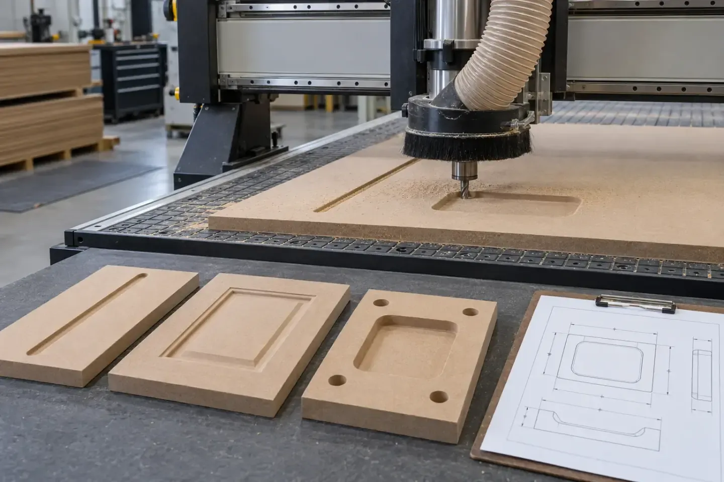
A CNC MDF quotation becomes production-ready when one controlled component definition covers MDF construction, file revision, face orientation, datums, profile geometry, machining depths, tolerances, delivered finish, quantity and pack sequence. First-part approval connects the drawing to repeat batch inspection.
Define exactly what the CNC supplier delivers
State the delivery stage before preparing the drawing package. CNC MDF supply can cover nested blanks, routed parts, drilled components, sanded profiles, paint-ready parts, faced components or completed cabinet-door fronts.
| Delivery stage | Scope to identify |
|---|---|
| Machined raw part | Cutting, routing, drilling and supplied raw edge condition |
| Sanded component | Machining plus defined face, edge and profile preparation |
| Finish-ready component | Preparation stage agreed with the coating or lamination process |
| Faced or coated component | Complete face, reverse, edge and protective-film construction |
| Assembly kit | Part IDs, hardware machining, labels, pack grouping and sequence |
Mark the visible face, reverse face, finished edges and assembly position. This gives every feature and inspection point a clear purpose.
Release one controlled drawing and file package
Use matching revisions across the 2D drawing, 3D model, CAD/CAM exchange file, cut list and part schedule. Identify which document controls dimensions when the file set contains different information.
| File control | Information to record |
|---|---|
| Units and scale | Millimetres or another named unit, plus 1:1 status for machine files |
| Part identity | Unique part code linked to quantity and pack label |
| Revision | Current letter or number, issue date and change description |
| Material code | MDF product, thickness and face construction |
| Orientation | Front, reverse, top, bottom and grain or pattern direction |
| Datums | Named face, edges and origin used for machining and measurement |
| Delivery state | Raw, sanded, primed, faced, coated or edge-finished |
A revision register helps purchasing, programming, production and inspection use the same released definition.
Separate input board size from finished component size
Record the source MDF format and the final dimensions of each component in separate fields. Input board format influences nesting, handling and yield; finished part dimensions control assembly and inspection.
For faced MDF, show the face and grain or pattern direction on the nesting drawing. Identify matching pairs, sequential panels and components whose orientation follows a cabinet elevation. For raw MDF, include any machining direction or face selection that affects the downstream finish.
Build coordinates from stable datums
Choose datum A as the controlling face and datum edges or centres for X and Y locations. Dimension holes, pockets, grooves, cut-outs and profiles from these named references. Dimension machining depth from the identified face.
Show front and reverse operations separately and add sections through stepped or opposing features. Overall size, squareness, centre lines, symmetry and mirrored or handed parts should appear directly on the controlled drawing. Inspection can then reproduce the same coordinate logic used by programming.
Describe every machined feature completely
A feature schedule turns visual geometry into machinable information.
| Feature | Define in the drawing |
|---|---|
| Through-cut | Contour, corner radius, edge relation and final size |
| Length, width, depth, bottom form and corner radius | |
| Groove | Width, depth, path, root shape and start/end position |
| Profile | Section view, radii, slopes, transitions and face orientation |
| Drilled hole | Diameter, depth or through status, coordinates and face |
| Chamfer or radius | Size, controlled edge and transition at corners |
Use section details at changes in depth and where several features meet. Attach each section to a part ID and drawing revision.
Coordinate geometry with cutter access
The selected cutter determines the smallest internal radius, groove root and accessible corner. Show the intended internal radii, square-corner relief where designed, narrow channels, deep pockets and clearance around adjoining faces.
Review cutter diameter, cutting length, shank clearance, tool projection and the path required to enter and exit the component. The supplier can then confirm a tool strategy that preserves the designed appearance and machining access.
Control machining depth and remaining MDF section
For every routed profile, pocket and opposing operation, state nominal board thickness, depth from the identified face and minimum remaining section. Map areas where a front route approaches a reverse pocket, hinge cup, connector hole, groove or edge profile.
The component designer should review the remaining material, hardware interface, support and load path. For paint-finished parts, include the radii and thin details in the coating trial because preparation and coating add their own geometry requirements.
Assign tolerances according to component function
Group dimensions by their effect on the finished assembly:
- **fit-critical dimensions** — hardware positions, mating grooves, connectors and assembly interfaces;
- **visual alignment dimensions** — repeated grooves, door gaps, adjacent profiles and matched elevations;
- **general dimensions** — overall sizes and features with wider functional allowance;
- **process reference dimensions** — values used to define geometry while another dimension controls acceptance.
State the tolerance, datum and inspection method for each critical or visual feature. Confirm the proposed values after the MDF construction, thickness, geometry, tooling, batch size and supplied finish are reviewed.
Review nesting, yield and part orientation
Provide quantities by part code and distinguish left/right or mirrored parts. The nesting plan should respect grain or pattern direction, visible-face orientation, required margins, tool clearance and any matched component sequence.
Compare yield using accepted finished parts per input board. Include test parts, setup pieces and agreed spare quantities as visible rows. A clear yield basis helps the quotation explain board consumption, machining time and the treatment of reusable offcuts.
Approve the first CNC-machined component
Select a first article that includes the most demanding features in the order: deepest route, smallest internal radius, opposing operations, critical hardware pattern, visible profile and finished edge.
The first-part report should record:
- part code, material code and drawing revision;
- overall dimensions and squareness;
- feature locations, depths, radii and remaining sections;
- face/reverse orientation and visual machining quality;
- fit trial with the specified hardware or mating component;
- approved corrections and resulting revision.
Retain the measured report, photographs and identified physical sample as the reference for batch release.
Control the batch through in-process inspection
Set inspection points after first setup, tool change, defined production intervals and final packing. Check the dimensions and visual features most sensitive to tool wear, datum movement, face reversal or part mix-up.
Link inspection results to machine, program revision, part ID and batch. Define the correction route for tool marks, chipped corners, dimensional variation and label errors. Production and inspection records then show which approved setup produced each packed component.
Label and protect machined MDF components
Group parts by cabinet, room, elevation, finish or installation sequence. Use part labels that show code, revision, orientation and quantity, placed on the protected back or external packaging.
Support routed faces and thin sections with suitable separators, edge protection and stable bundle bases. Record pack dimensions, gross weight, lifting points and unloading method. For sequenced or matched parts, keep installation order visible from production through receiving.
Buyer review checklist
A CNC MDF inquiry is ready for quotation when it includes:
- MDF product, thickness, face/reverse construction and supplied finish;
- input board format and finished component dimensions;
- controlled 2D drawing, machine file and part schedule with matching revisions;
- units, datums, front/reverse orientation and grain or pattern direction;
- complete feature geometry, depths, radii and remaining sections;
- fit-critical, visual and general tolerances with inspection methods;
- quantities, handed parts, nesting constraints and spare-part requirement;
- first-article approval and hardware or assembly trial;
- part labels, pack sequence, protective materials and destination.
Keep every supplier clarification and accepted change in the released revision package.
Request an MDF quotation
Send the current CNC file package, material requirement, part quantities, delivered finish, tolerance schedule, sample requirement, labels, packing and destination. The CNC MDF Processing page covers the service scope; request a drawing review with the files that control the proposed order.