
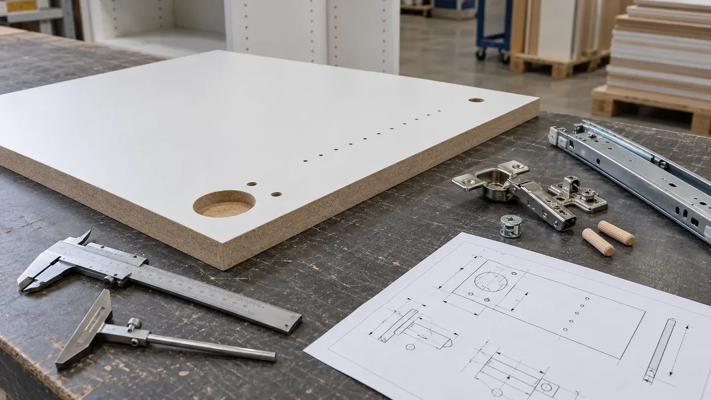
Coordinate MDF drilling with the exact hinge, connector, runner, handle, insert or fastener used in the assembly. A drawing-linked hardware schedule should control hole type, diameter, depth, entry face, datum position, handed component and first-assembly result before repeat machining begins.
Start with the exact hardware system
Build the hole pattern from the selected hardware manufacturer’s current installation drawing or confirmed physical hardware. Record brand, series, model, size, mounting plate, insert, screw or connector, quantity per component and document revision.
| Hardware group | Information to connect to the MDF part |
|---|---|
| Concealed hinge | Cup, fixing points, mounting plate, overlay or inset geometry and adjustment range |
| Drawer runner | Runner model, cabinet and drawer reference planes, fixing pattern and handed side |
| Cam or connector | Bore diameter, depth, cross-hole position, orientation and mating dowel |
| Dowel | Diameter, insertion depth, spacing and mating-part position |
| Handle or pull | Hole centres, through-hole size, face orientation and visible alignment |
| Insert or direct screw | Insert type or screw reference, pilot requirement, engagement and installation method |
Link every hardware line to the component IDs it affects. This keeps a later hardware change visible across drawings, machining and inspection.
Name the front, reverse and datum edges
Mark the visible front, reverse, top, bottom and datum edges on every part drawing. Assign datum A to the controlling face and datum B/C to the edges used for X and Y coordinates.
Give left-hand, right-hand and mirrored parts unique IDs. Add an orientation symbol to the drawing and part label. For decorative surfaces, show grain or pattern direction alongside the hardware orientation so machining and assembly follow the same component view.
Use a complete callout for every hole
A drilling schedule should identify the geometry, position and inspection basis of each feature.
| Hole information | What to record |
|---|---|
| Feature ID | Unique callout linked to hardware and part code |
| Form | Blind, through, countersunk, counterbored, stepped, slotted or paired |
| Size | Diameter, depth, step dimensions and bottom form where relevant |
| Position | X and Y coordinates from named datums |
| Entry | Front, reverse or edge entry face |
| Relationship | Edge distance, pitch and spacing to neighbouring features |
| Acceptance | Tolerance, inspection method and drawing revision |
Show sectional views for blind, stepped and intersecting holes. The section makes the remaining material and relationship to the surface construction visible.
Coordinate hole depth with board thickness
State nominal and accepted board thickness, hole depth and the remaining MDF section below every blind operation. Review hinge cups, deep connector bores, inserts and opposing holes together.
For faced or coated components, include the surface construction in the thickness review. The selected hardware and part designer should confirm engagement, clearance and remaining material for the finished assembly. Use a depth gauge or agreed checking method during first-part and batch inspection.
Review edge distance and nearby features
Overlay the drilling pattern with cut edges, routed profiles, grooves, pockets, cut-outs, joints and edge-banding routes. Sections through crowded areas reveal where a hole approaches another feature or a thin remaining web.
Define the relationship from functional datums and confirm it through the representative assembly. Door hinges, cam connectors, shelf pins and drawer-runner screws each create different geometry and load paths, so each hardware group should retain its own approved drawing reference.
Plan drilling for raw and faced MDF
Record whether drilling occurs in raw MDF, melamine-faced MDF, veneered MDF, painted components or another finished construction. Surface condition affects entry-face protection, chip control, protective-film handling and the appearance of through holes.
Identify the visible entry and exit faces, specify any countersink or finished rim, and define the accepted appearance around the opening. For grain- or pattern-directed panels, retain orientation from nesting through drilling and packing.
Define the fastening method with the furniture design
State whether assembly uses direct screws, inserts, dowels, cams, confirmat-style connectors, hinges, brackets or a combined system. Record the installation tool, tightening or insertion control where specified by the hardware provider, and the intended assembly sequence.
The furniture or hardware designer should confirm component support, fastener engagement, spacing, load path and service requirement. An assembly trial with the actual board, hardware and mating components provides the project-specific fit reference.
Control repeated hole patterns
System holes for shelf pins, runners or adjustable furniture should use a named pitch, origin and termination point. Identify the first and last hole, skipped positions, front setback, row spacing and component orientation.
For repeated doors or cabinets, connect the pattern to the same master datum across all related components. This supports consistent gaps, runner alignment and interchangeability during assembly.
Approve a complete first-assembly set
Produce a representative left/right or mirrored set using the actual MDF construction and hardware. Include the mating side, door, drawer or connector part so the review covers the full interface.
Check:
- component orientation and part identity;
- hole diameter, depth and datum position;
- hardware installation and seating;
- door, drawer or joint alignment;
- movement, adjustment range and clearances;
- visible surface condition around holes;
- assembly sequence and access for tools.
Record the result against the drawing and hardware revisions. Release accepted changes through a new controlled revision before the repeat batch.
Inspect drilling during repeat production
Define inspection after initial setup, tool change and planned batch intervals. Critical patterns can use dedicated gauges, programmed coordinate measurement or another agreed method; blind-hole depth should use a suitable depth check.
Record part ID, hardware feature, drawing revision, sample quantity, measured values and disposition. Include visual checks for breakout, raised surface around the entry, plugged holes, incorrect face and mixed handed parts. Link the report to the production batch and pack labels.
Manage hardware and drawing changes together
A hardware substitution can change cup position, fixing pattern, pilot diameter, insertion depth, plate height, clearance and component gap. Use one change record that identifies the old and new hardware, affected part codes, revised drawings, sample requirement and effective production batch.
Quotations should state the hardware and drawing revisions used for pricing. Purchase orders and inspection records should carry the same references so the released configuration remains clear through delivery.
Label and protect drilled components
Label each part with code, revision, orientation, quantity and cabinet or kit group. Place labels on the protected back or external packaging. Keep left/right components and matched sets clearly separated.
Use separators, face protection, stable bases and edge support suited to the finished surface and hole geometry. Small machined parts and hardware kits should follow the assembly grouping shown in the pack list. Record pack weight, lifting method and receiving sequence for large orders.
Buyer review checklist
An MDF drilling inquiry is ready for quotation when it identifies:
- exact hardware manufacturer, model and installation reference;
- MDF product, thickness and face/reverse construction;
- component IDs, left/right orientation and grain or pattern direction;
- datums, hole form, diameter, depth, coordinates and entry face;
- remaining section, edge distances and intersections with routed features;
- fit-critical tolerances and inspection methods;
- representative first-assembly set and approval record;
- drawing and hardware revision control;
- part labels, pack grouping, quantity and destination.
Keep the approved hardware sample, drawing set and assembly record connected to the order revision used for batch production.
Request an MDF quotation
Provide the MDF construction, thickness, finish, part list, controlled drawings, hardware schedule, physical hardware where needed, quantities, labels, packing and destination. Use Cut-to-Size MDF for rectangular parts and CNC MDF Processing for mixed drilling, routing and profiling requirements.