
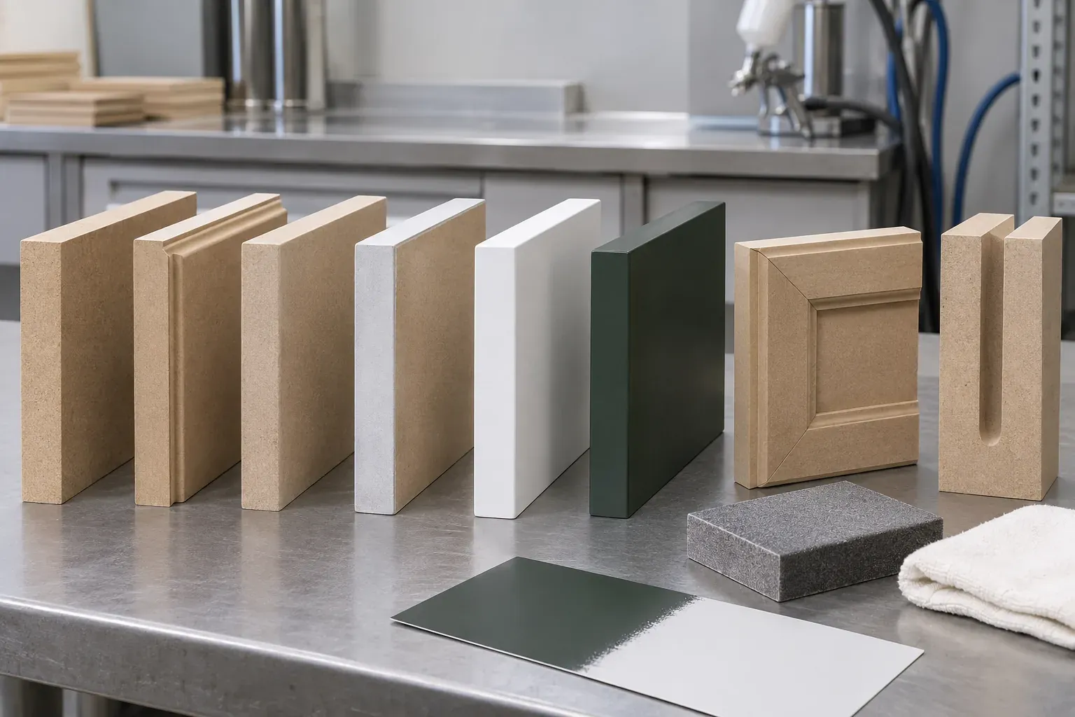
A smooth painted MDF edge comes from suitable MDF, clean machining, geometry-specific sanding, complete dust removal, compatible sealing and priming, and a representative finish trial. Define preparation and inspection for faces, straight edges, routed profiles, grooves and drilled openings.
Why MDF edges finish differently from the face
Factory-sanded MDF faces are compressed and relatively uniform. Cutting or routing exposes the fibre structure through the board thickness, so the edge can absorb sealer and primer differently and can show raised fibres after the first wet coating layer.
Treat the finished component as a group of distinct surfaces:
| Surface | Main preparation question |
|---|---|
| Factory face | Is the supplied sanding level suitable for the coating system? |
| Straight cut edge | Is it flat, square and free from torn fibre or saw marks? |
| Routed profile | Are tool marks removed while the designed radius and detail remain intact? |
| Groove or inside corner | Can dust, sealer and coating reach the full geometry evenly? |
| Drilled or hardware opening | Is exposed fibre prepared where the opening remains visible or exposed? |
This separation gives each area a clear process and acceptance standard.
Define the delivered finish condition first
State whether the supplier delivers raw cut parts, sanded components, sealed parts, primed components or a complete top-coated product. The requested stage determines which party controls sanding, cleaning, coating compatibility, curing and appearance approval.
For a finished painted component, specify visible faces and edges, gloss level, colour reference, profile definition, hardware openings, assembly interfaces and the surfaces that remain concealed. For a paint-ready component, define the agreed preparation stage and the coating trial used to confirm it.
Choose the MDF and profile as one system
Confirm MDF product, thickness, density range, supplied face condition and the deepest routed section before the coating process is approved. A deep profile, small radius or thin remaining section exposes and stresses a different part of the board compared with a straight cut edge.
Review the edge quality on the actual offered MDF. Paint Grade MDF supports finish-led sourcing, while Sanded MDF defines a controlled raw surface for further processing. The coating provider should qualify the complete MDF, preparation and paint combination used for the order.
Create a clean machined edge before sanding
Inspect the raw component under side lighting and by touch. Look for torn fibre, chatter, burning, steps between tool passes, breakout at corners, compressed edges and variation between the entry and exit of a cut.
Tool condition, geometry, rotational speed, feed rate, cutting direction, extraction and component support all influence the starting surface. Record the approved machining setup for repeated parts. Sanding then refines the clean, consistent machined edge.
Use a sanding sequence matched to the geometry
Establish the abrasive grade sequence, machine or hand method and number of passes through the selected MDF and coating trial. Record the approved result as the production setting for that construction.
| Area | Control during sanding |
|---|---|
| Straight edge | Flatness, square corners and even fibre removal |
| External radius | Consistent radius from part to part |
| Routed profile | Tool-mark removal with retained peaks, valleys and shadow lines |
| V-groove | Clean point and consistent groove width |
| Inside corner | Full access with the adjoining detail retained |
| Face-to-edge transition | Smooth transition with the approved corner character |
Inspect after each stage under consistent light. The approved profile drawing and finished sample define how much detail remains.
Clean and condition the component before sealing
Remove sanding dust from faces, edges, grooves, holes and internal corners using the cleaning method accepted for the coating system. Handle prepared parts with clean supports and gloves where the finish process requires them. Record the maximum interval between preparation, sealing and priming if the production process controls that timing.
Coating trials should use the expected workshop temperature, humidity, application equipment and cure conditions. This connects the approved appearance to a repeatable production environment.
Select sealer and primer with the coating system
Sealer or primer should suit the MDF, the exposed edge and the following coating layers. Review edge wetting, fibre raise, build, sandability, adhesion between layers, drying or cure conditions and compatibility with the selected topcoat.
Waterborne, solvent-borne, two-component and UV-curing systems can use different preparation and cure processes. Follow the coating supplier’s current technical instructions and qualify the proposed materials together on the actual component. Record product references, mixing or activation requirements where applicable, application method, layer sequence and cure stage.
Build and sand the coating while retaining profile detail
After the first sealed or primed layer, inspect the edge for raised fibre, open texture, pinholes, sink-back and uneven build. Intermediate sanding should create a uniform surface for the next layer while retaining the intended geometry.
Measure the result through appearance, coverage and profile consistency. The accepted system should state the sequence of preparation, sealer or primer, intermediate sanding and topcoat, together with the supplier instructions that control film application and cure.
Use defects to identify the process stage to adjust
A defect table helps production trace the source before the next batch.
| Observed condition | Process areas to review |
|---|---|
| Fuzzy or raised edge | Raw machining, abrasive sequence, cleaning and first wet layer |
| Visible tool lines | Cutter condition, feed, support and initial sanding |
| Pinholes or open texture | Dust removal, sealer wetting, build and intermediate sanding |
| Sink-back after curing | Layer build, drying or cure interval and edge absorption |
| Rounded profile detail | Sanding tool, pressure, access and number of passes |
| Face-to-edge colour or gloss difference | Preparation, primer build, topcoat application and viewing angle |
| Cracking at a sharp feature | Profile geometry, remaining section, coating build and handling |
Record the condition with part ID, location, lighting and process stage so correction targets a defined cause.
Approve a representative finished component
Select a first article containing the deepest route, smallest approved radius, longest visible edge, inside corner, groove and visible hardware opening used in the order. Finish the complete component through the proposed production sequence.
Approve colour, gloss, smoothness, fibre visibility, profile definition, face-to-edge transition and appearance under the agreed lighting and viewing orientation. Give the sample an ID and connect it to the drawing, MDF product, coating references and order revision. A flat colour chip remains useful for colour; the finished component controls how the system appears on real geometry.
Control batch inspection and protective packing
Set inspection points after machining, raw sanding, sealing or priming and final coating. Use the same lighting, orientation and viewing distance established at approval. Record acceptable limits for fibre visibility, sanding lines, pinholes, edge build, colour, gloss and profile consistency, together with the agreed repair method.
After curing, use clean face separators, edge protection, supported stacking and packaging materials compatible with the finished coating. Place labels on the protected back or outer packaging and identify part, finish, orientation, quantity and pack sequence.
Buyer review checklist
A paint-edge specification is ready for quotation when it identifies:
- MDF product, thickness and supplied face condition;
- component drawing, revision and visible surfaces;
- straight edges, profiles, grooves, corners and openings requiring preparation;
- raw machining and sanding acceptance points;
- sealer, primer and topcoat system or the party responsible for selecting it;
- representative first-article geometry and physical sample ID;
- colour, gloss, profile and edge appearance criteria;
- batch inspection stages, repair method, curing and pack protection;
- quantity, component labels, destination and delivered finish stage.
Keep the approved component and process record together so repeat production uses the same material, geometry and finish basis.
Request an MDF quotation
Send the MDF product, thickness, component drawing, routed geometry, visible surfaces, delivered finish stage, coating references, sample requirement, quantity, packing and destination. Use the MDF cabinet door processing guide for routed fronts or request a specification review for the proposed substrate and finish construction.