
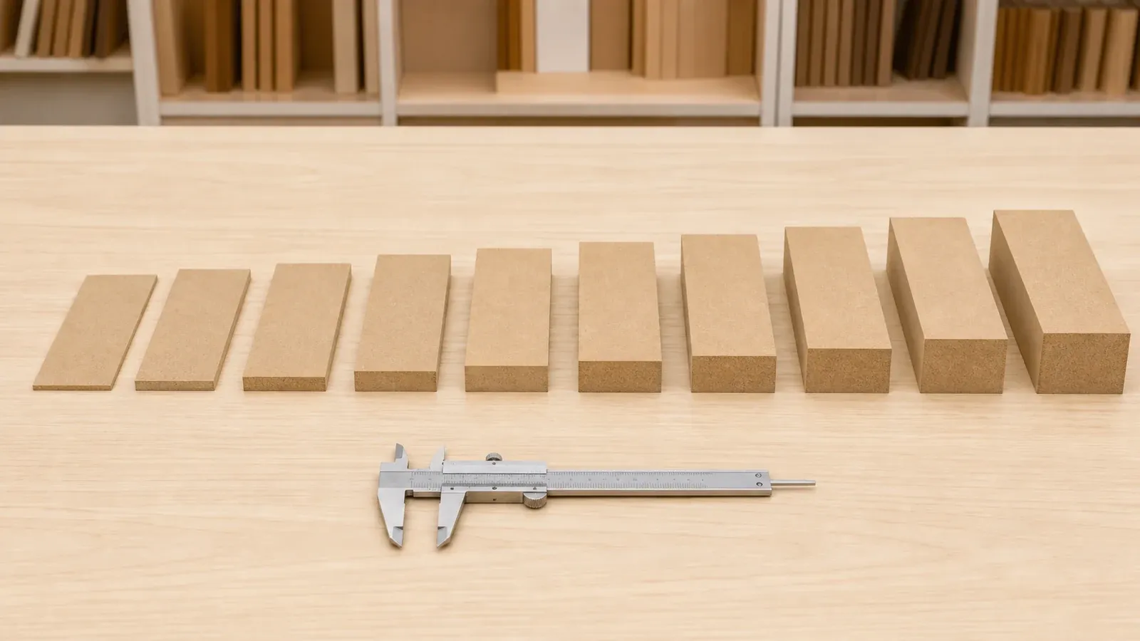
Choose MDF thickness from the finished component, span and support, machining depth, hardware interface, panel weight and handling plan. Thin and thick MDF serve different component geometries and production processes, with density and weight changing across the thickness schedule.
Separate the thickness ranges before comparing
CUZI MDF uses distinct pages and density schedules for the main thickness-led purchasing options.
| Purchasing option | Thickness range | Typical decision focus |
|---|---|---|
| Thin MDF Board | 2–11 mm | Supported backs, drawer bottoms, decorative liners, door skins, lamination substrates and display parts |
| Raw MDF | 12–18 mm within the general range | Standard furniture panels, substrates and components selected through the complete Raw MDF specification |
| Thick MDF Board | 19–35 mm | Substantial components, deep routing, edge profiling, display bases and thickness-led industrial orders |
The finished component determines the relevant route. Record its dimensions, support, orientation, machining, hardware, surface and handling before selecting the nominal thickness.
Use a thickness decision sequence
Select the thickness through the finished part in a fixed order.
| Decision step | Information to define | What it controls |
|---|---|---|
| 1. Component geometry | Length, width, orientation, openings and edge shape | Relevant thin, standard or thick MDF option |
| 2. Support and loading | Clear span, support positions, fixing and expected use | Stiffness review and representative assembly |
| 3. Machining section | Grooves, rebates, pockets, routes and opposing cuts | Required overall thickness and remaining section |
| 4. Hardware interface | Hinge, runner, connector, insert and edge distance | Hole depth, fixing zone and finished component weight |
| 5. Surface construction | Raw, painted, veneered, laminated or faced panel | Finished thickness, face balance and edge treatment |
| 6. Production and logistics | Board format, nesting, machine access, bundle weight and unloading | Order format, usable yield and handling plan |
This sequence turns thickness into a component decision shared by design, purchasing, machining, assembly and logistics teams.
Compare current supply parameters
Use thickness-specific data in the quotation and weight plan.
| Product range | CUZI MDF density schedule | Indicative price | Supplied surface |
|---|---|---|---|
| 2–4 mm Thin MDF | 800–810 kg/m³ | US$190–350 per m³ | Smooth sanded faces for downstream processing |
| 5–8 mm Thin MDF | 780–800 kg/m³ | US$190–350 per m³ | Smooth sanded faces for downstream processing |
| 9–11 mm Thin MDF | 760–780 kg/m³ | US$190–350 per m³ | Smooth sanded faces for downstream processing |
| 19–35 mm Thick MDF | 650–680 kg/m³ | US$158–219 per m³ | Raw or sanded faces for the confirmed finish construction |
The nominal thickness tolerance is ±0.1 mm, subject to the confirmed measuring and acceptance method. E0, E0.5 and E1 options are specified with the applicable test standard, product scope and destination requirement. Final price follows the exact thickness, size, density, emission class, surface, quantity, processing, packing and delivery basis.
Translate nominal board thickness into the finished construction
The purchased MDF thickness is one layer in the finished part. Veneer, melamine, laminate, primer, topcoat, adhesive and edge materials can change the final dimensions and the fit with grooves, hardware and adjoining components.
Record three values separately:
1. **MDF core thickness** and its agreed tolerance; 2. **complete face and reverse construction**, including adhesive or coating build where it affects fit; 3. **finished component thickness** at the inspection point used for assembly.
Use the same datum face and measurement locations on the drawing, first component and production inspection record. This keeps groove width, edge band, hardware depth and adjoining-part alignment tied to the supplied construction.
Calculate sheet weight from the selected density band
Use **thickness × length × width × density** for theoretical net sheet weight. Enter metres for every dimension and kg/m³ for density.
| Example sheet | Density used | Calculated net weight before packing |
|---|---|---|
| 3 mm × 1220 × 2440 mm | 800–810 kg/m³ | 7.1–7.2 kg |
| 6 mm × 1220 × 2440 mm | 780–800 kg/m³ | 13.9–14.3 kg |
| 9 mm × 1220 × 2440 mm | 760–780 kg/m³ | 20.4–20.9 kg |
| 25 mm × 1220 × 2440 mm | 650–680 kg/m³ | 48.4–50.6 kg |
| 35 mm × 1220 × 2440 mm | 650–680 kg/m³ | 67.7–70.8 kg |
Facings, coatings, labels and packaging add weight separately. Use the confirmed production density and actual bundle construction for order, loading and unloading plans. The MDF sheet weight and CBM calculator supports other thicknesses and formats.
Let the component and support define thickness
Connect thickness to the way the finished part works.
| Component | Thickness review points |
|---|---|
| Furniture back or drawer bottom | Groove fit, perimeter support, fixing method, panel dimensions and assembly movement |
| Door skin or decorative liner | Bonding construction, substrate support, pressing process, flat handling and finished edge |
| Shelf or horizontal panel | Clear span, load, support positions, edge construction and furniture design |
| Routed door or profiled component | Overall thickness, deepest cut, opposing machining and minimum remaining section |
| Display base or substantial furniture part | Geometry, fixing, finished weight, lifting and floor or frame interface |
The component drawing should show support points, joint and hardware interfaces, service openings and the orientation used in assembly. A representative assembly can then confirm the selected construction.
Validate span, support and finished weight together
Thickness contributes to component stiffness, while the finished result also depends on length, width, orientation, support spacing, openings, edge construction, surface layers and expected loading. Record these inputs on the component drawing and review the actual assembly under its intended support arrangement.
For shelves and long horizontal parts, the trial should use the intended clear span, fixing positions and representative load. For doors and moving components, include the finished face construction, edge treatment and hardware because they determine operating weight. For backs and drawer bottoms, reproduce the groove, perimeter support and fixing pattern. The approved assembly then becomes the reference for production release.
Control machining depth and remaining section
Thin sheets benefit from continuous machine support, stable feeding, suitable tooling and controlled collection of narrow strips or small parts. Thick MDF can support deeper profiles, while every route, pocket and opposing cut reduces the local remaining section. Add a section view to the drawing with overall thickness, each machining depth, internal radius and minimum remaining material. Review multi-pass tooling, edge quality and the most demanding profile through a first component before repeat production.
Coordinate thickness with hardware and joints
Thickness changes the available material around hinge cups, connector holes, inserts, grooves, rebates and edge fixings. Identify the hardware reference, hole diameter and depth, pilot-hole requirement, insertion direction, edge distance and datum face on the released drawing. Review finished weight with the actual hinge, runner, bracket or support system. Representative component and assembly testing establishes the suitable hardware option for the selected board and geometry.
Compare format yield with factory handling
Reference board formats are 1220 × 2440 mm, 2100 × 2800 mm, 1830 × 3660 mm, 1830 × 2440 mm, 2440 × 3660 mm and 1830 × 4200 mm. A larger format may improve nesting for long or repeated parts while increasing full-sheet weight, storage area, machine-loading requirements and bundle support needs. Compare usable yield together with trim allowance, grain or finish direction, offcuts, machine envelope, lifting equipment and destination unloading. Confirm each thickness-and-format combination in the quotation.
Compare the cost of usable components
A cubic-metre or sheet price becomes commercially useful after it is connected to part yield and factory handling. Compare each option through:
**board cost + surface construction + cutting and machining + handling + inspection + packing + expected production loss ÷ accepted component quantity**
Thin sheets may require additional support during feeding, stacking and transport. Thick sheets increase individual sheet weight and may reduce the number handled in one lift or bundle. Large formats can improve nesting while changing machine access and unloading needs. Use the actual cutting plan and approved bundle design to compare total component cost across thickness and format options.
Match the surface process to faces and edges
Thin MDF can provide smooth sanded faces for melamine pressing, painting, laminating and other downstream processes. Thick MDF can support painting, veneering, laminating and routed profiles when the complete process is qualified. Define both supplied faces, visible face, edge or routed-profile preparation, adhesive or coating system and finished appearance. Use a representative sample containing the face, cut edge and deepest profile included in the production order.
Design packaging around stiffness and weight
Thin full sheets and cut parts need flat continuous support, suitable bearer spacing, aligned edges, cover boards and controlled strap pressure. Thick panels need bundle quantities and base supports matched to their higher individual weight, along with lifting and unloading access. State full-sheet or component dimensions, quantity by thickness, surface sensitivity, bundle-weight target, labels, destination and handling equipment. Add packaging weight to the confirmed net panel weight for transport planning.
Inspect thickness from production to receiving
Use one documented method across sample approval, production inspection and destination receiving. The record should identify the product, nominal thickness, tolerance, measuring instrument, measurement locations, conditioning state, sample quantity, board format, batch and bundle number.
Measure representative sheets away from visibly damaged edges and use the agreed face references. For surfaced panels, state whether the acceptance value applies to the MDF core or the complete faced construction. Link out-of-range findings to the affected batch and component fit, then retain the inspection record with the approved sample, drawings and packing list.
Prepare a thickness-led RFQ
Provide the information that controls both material selection and production:
- finished component, dimensions, orientation and service environment;
- selected Thin MDF, Raw MDF or Thick MDF option;
- nominal thickness and ±0.1 mm tolerance requirement;
- board format and finished-part dimensions;
- applicable thickness-specific density band;
- E0, E0.5 or E1 destination requirement;
- span, support, joint and hardware details;
- routing, drilling, pockets, grooves and minimum remaining section;
- supplied face, downstream finish and sample requirement;
- quantity by thickness and part number;
- packaging, bundle weight, destination and unloading method.
Capacity is 300 m³ per day for each thickness. The normal MOQ is 1 × 20'GP for each individual specification, and normal production lead time is 7–15 days after the complete specification and commercial requirements are confirmed. Use the Thin MDF Board product page, Raw MDF product page and Thick MDF Board product page for current supply details. Request a specification review with the component, quantity and destination.
Buyer review checklist
Before relying on this guidance, record the finished component, service environment, MDF product or unresolved product requirement, thickness, dimensions, supplied surface, visible edges, machining, hardware, quantity and destination. Identify which values need current technical documents and test reports and which appearance decisions need a physical sample.
For international supply, also confirm drawing and sample revisions, packaging construction, part or bundle labels, handling limits, required documents and the party responsible for finished-product design and destination compliance. Ask the supplier to list unresolved items and exclusions in the quotation, and keep every missing value visible for confirmation.
Compare quotations only after these inputs have been normalized. Check whether the offered price covers a full board, a faced construction, a machined part or a finished component, and whether samples, secondary work, protective materials and documentation are included. Record every change after approval so purchasing, production, inspection and receiving teams use the same revision.
Typical lead time is 7–15 days after requirements are confirmed. Final timing depends on specification, quantity, production scheduling and destination. This planning range covers production; arrival timing also depends on the confirmed logistics route.
Request an MDF quotation
Share the application, specification, quantity, packaging and destination with CUZI MDF for an order-specific review.