
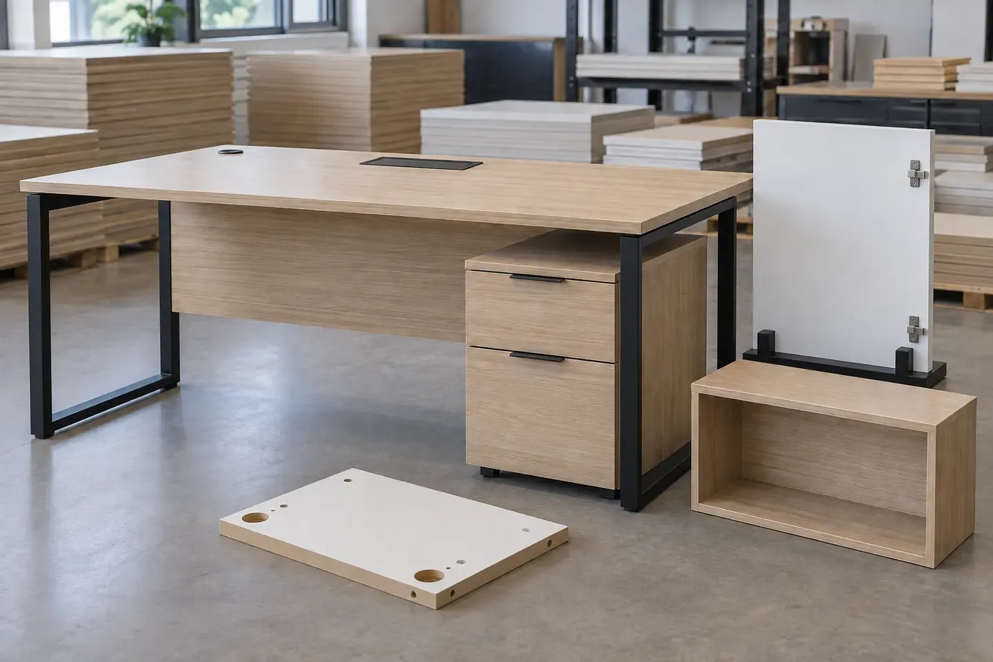
Office furniture production turns desks, worktops, pedestals, storage, meeting tables and screens into repeat component families. A controlled schedule connects each part to its MDF construction, finish, edge, cable feature, hardware, revision, quantity and installation pack.
Start with the office furniture range and quantities
List workstation types, desk sizes, returns, pedestals, storage units, meeting tables, screens and shared components. Record the quantity of each finished unit and the installation phase or location. This converts a room layout into a production schedule with traceable product-family IDs.
Create a component-family schedule
Separate every repeated part by its construction and processing.
| Component family | Main decisions |
|---|---|
| Worktop or meeting top | Finished size, support, face/reverse, edge, cable features and weight |
| Modesty or screen panel | Dimensions, visible faces, fixing points and edge construction |
| Pedestal or drawer part | Runner system, lock, handle, drilling and handed side |
| Storage carcass or shelf | Thickness, support, connector pattern and finish |
| Door or drawer front | Surface reference, grain direction, edge, gaps and hardware |
| Plinth, filler or end panel | Site dimension, finish continuity, levelling and installation joint |
Assign material, thickness, finish, edge, hardware, quantity and drawing revision to every part code.
Specify the complete panel construction
Record MDF product, nominal and finished thickness, dimensions, face material, reverse material, edge treatment and supplied processing stage. State whether the order covers full panels, cut parts, edge-banded components, drilled parts or assembly-ready sets. Use the same construction code on the quotation, drawings and part schedule.
Define worktop geometry and support
Show top length, depth, finished thickness, corner shape, overhangs, leg or frame positions, modesty-panel connection and adjoining returns. Relate the finished component weight and support layout to the furniture design. Include the actual edge profile and underside interfaces in the first-article review.
Specify visible and working surfaces
Record face and reverse construction, colour, texture, gloss, grain direction and edge treatment. Describe the expected touch, cleaning and visual conditions for worktops, fronts and shared surfaces. Approve physical panels, edges and adjoining corners under representative office lighting.
Coordinate edges, corners and exposed openings
Define straight edge bands, rounded or chamfered edges, corner radii, finger pulls and the finished surfaces inside cut-outs. Mark which edges remain visible after assembly. Use a physical corner sample to review colour, texture, gloss, joint line and touch quality.
Coordinate cable, power and service details
Show every service feature in the controlled drawings.
| Feature | Information to define |
|---|---|
| Cable port | Shape, size, position, insert and finished edge |
| Power-module cut-out | Equipment reference, cut-out, fixing and clearance |
| Wire channel | Route, depth, cover, exit position and support zone |
| Access panel | Opening direction, fixing, gap and removable-part ID |
| Screen or divider fixing | Bracket reference, hole pattern and reinforcement or support detail |
Review each opening with the actual accessory or current interface drawing.
Control hardware and connector patterns
Link runners, hinges, locks, connectors, levellers and handles to part IDs. Use named datums for hole diameter, depth and coordinates. Separate left and right parts, visible faces, blind holes and through operations. Keep the current hardware drawing with the matching component revision.
Control mirrored and handed components
Mark left, right, front, back, top and visible face on drawings and cut lists. Use distinct part codes for mirrored drilling or edge work. Carry those identities through nesting, machining, inspection, packing and installation so visually similar parts remain distinguishable.
Approve a representative workstation or storage unit
Assemble or dry-fit one representative product containing the selected panels, finished edges, cable feature, hardware and support. Review dimensions, squareness, gaps, movement, hardware adjustment, edge appearance, service access and assembly sequence. Record the accepted parts and drawing revisions before repeat production.
Plan repeatability and replacement parts
Keep stable references across production, later phases and future additions.
| Control item | Repeat-order record |
|---|---|
| Surface | Physical sample ID and supplier reference |
| Edge | Material, colour, thickness and joint sample |
| Part | Drawing, cut-list and machining revision |
| Hardware | Manufacturer, model and installation drawing |
| First article | Accepted unit, component photos and inspection record |
| Packaging | Pack ID, contents and installation phase |
Inspect first articles and batch parts
Connect inspection results to the repeated part identity.
| Inspection area | Review point |
|---|---|
| Material and surface | Construction code, physical reference, face/reverse and direction |
| Dimensions | Finished size, squareness, corner radius and thickness |
| Processing | Holes, cut-outs, channels, edges and handed orientation |
| Assembly | Connector fit, gaps, movement, alignment and support interfaces |
| Identification | Product family, part code, revision, quantity and pack assignment |
Manage revision changes across a batch
Record the effective date or production quantity for each approved drawing, finish or hardware change. Identify affected product families and part codes. Use one released revision for production, inspection and packing records, and keep replacement parts linked to the same finished construction.
Pack for project installation
Group parts by workstation, storage unit, room, floor or installation phase. Protect worktop faces, exposed edges, corners and high-gloss surfaces with stable supports and suitable separators. Keep outer labels readable and align every packing list with the product-family and component schedules.
Buyer review checklist
Before releasing an office furniture MDF order, confirm:
- finished units and quantities are grouped by product family;
- every repeated part has a construction code, drawing and revision;
- worktops connect dimensions, support, edge and cable features;
- faces, reverses, finishes and grain directions use physical references;
- cable openings and power interfaces match current accessory information;
- hardware drilling separates handed, blind and through operations;
- one representative unit verifies assembly and adjustment;
- first-article and batch inspection use the same part identities;
- packs follow the room, floor or installation sequence.
Prepare the office-furniture RFQ
Send the product-family schedule, component drawings, MDF construction codes, finishes, edges, cable and power details, hardware, quantities, first-article scope, inspection, pack grouping and destination. Use MDF for Office Furniture for the application guidance, review Cut-to-Size MDF and CNC MDF Processing for component supply, then request a production review.
Request an MDF quotation
Share the application, specification, quantity, packaging and destination with CUZI MDF for an order-specific review.